32DF9T02.B
3 - 8
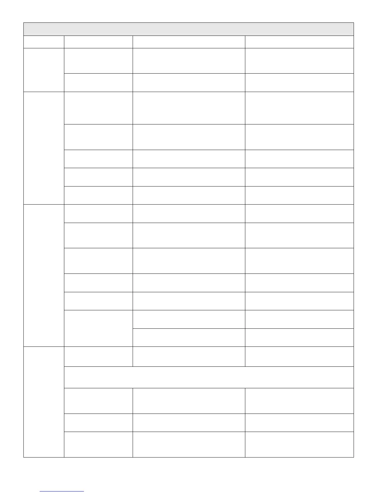
TABLE 3-1: WHEELCHAIR AND STANDEE LIFT TROUBLESHOOTING CHART
SYMPTOM PROBABLE CAUSE TESTS AND CHECKS CORRECTIVE ACTION
Down valve failure. Check for 24 vdc at terminal 4 on TS1
(located in pump enclosure).
If voltage is not present, replace
down valve (or replace entire
hydraulic pump assembly).
Debris in hydraulic
system.
Look for fluid returning to pump reser-
voir after button is released.
If fluid is seen, flush hydraulic system.
“Deployed” indicator
switch misadjusted.
Check for 24 vdc at pin 5 of P5. If voltage is not present, verify ad-
justment (switch is located at right
rear of carriage, with its plunger pro-
truding through right side).
Connector for rollstop
switches is loose.
Check for 24 vdc at pin 5 of J6. Verify secure connection of P6 and
J6 (connector is behind left rollstop
cover; Fig 3-3 in chapter 4).
“Up-Down” switch (on
control panel) failure.
Check for 24 vdc at pin 3 of P1 with
“Up” button pressed.
If voltage is not present, replace
switch (section F-1 of chap 3).
“Rollstop Closed”
switch failure.
Check for 24 vdc at pin 13 of P5. If voltage is not present, replace
switch (section F-1 of chap 4).
Rollstop
does not
close when
“Up” button
is pressed.
Rollstop motor failure. Check for 24 vdc between pins A and
B of J7.
If voltage is present, replace rollstop
motor.
A load of 75 lbs, or
greater, is on platform.
Check for presence of an object on
platform.
Remove object.
Main harness connec-
tor on controller is
loose.
Check for 24 vdc at pin 2 of P5. Verify secure connection of P2 to
controller.
Carriage-platform har-
ness connector on con-
troller is loose.
Check for 24 vdc at pin 2 of P5. Verify secure connection of P5 to
controller.
“In-Out” switch failure
(on control panel).
Verify 24 vdc at pin 2 of P1. If voltage is not present, replace “In-
Out” switch (section F-1 of chap 4).
In/Out motor failure. Check for 24 vdc across In/Out motor
(motor moves carriage).
If voltage is present, replace In/Out
motor.
Check for 24 vdc at pin 2 of P2 with
“In” button pressed.
If voltage is present, replace control-
ler.
Platform
does not
stow when
“In” button
and Stow
Guard but-
tons are
pressed.
Controller
failure.
Check for 24 vdc between pins 10 &
15 of P5 with “In” button pressed.
If voltage is not present, replace con-
troller.
Hydraulic manual
release valve is open.
Look for fluid returning to pump reser-
voir while pumping.
Close manual release valve; do not
over-tighten.
CAUTION
Verify 24 vdc power to lift is off before opening this hydraulic line. Support platform if deployed.
Manual backup pump
failure.
Loosen the fitting on hydraulic line that
is connected to pump assembly, and
then operate backup pump.
If fluid does not flow, replace manual
backup pump (or replace entire hy-
draulic pump assembly).
Hydraulic hose or
fitting leak.
Check for an oil accumulation in bot-
tom of enclosure, or in pump box.
Tighten hydraulic fitting or replace
hydraulic hose.
Manual
backup
pump does
not raise
platform.
Down valve is open. Remove down valve (part of hydraulic
pump assembly) and check for internal
debris or damage.
Clean or replace down valve (or en-
tire hydraulic pump assembly).
 Loading...