32DF9T02.C
4 - 6
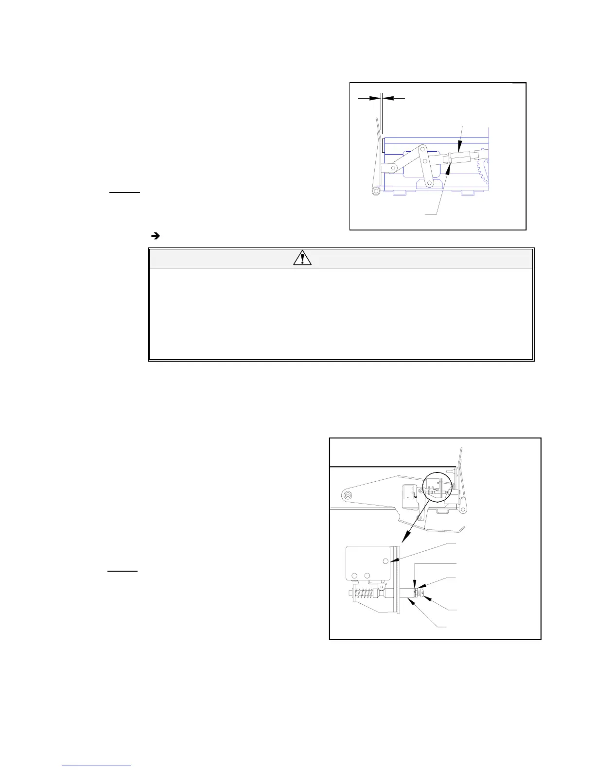
6) Refer to Figure 4-6. Loosen jam-nut and adjust the link length by turning the center sec-
tion. Adjust link so that rollstop closes to within 1/32" of rubber bumper (that rollstop con-
tacts). Rotating the center section counterclockwise (viewed from rollstop) shortens the
link, and turning it clockwise lengthens it.
7) Re-install right rollstop cover and manual
rollstop control knob.
8) Reconnect positive battery cable at vehicle
battery compartment.
d. Rollstop “Closed” Switch Adjustment
NOTE:
Refer to Electrical Controls section if re-
placement of rollstop “Closed” switch is
necessary.
1) Deploy platform using control pendant
(
/OUT), and then support.
WARNING!
•• WEAR PROTECTIVE CLOTHING AND EYE PROTECTION AT ALL TIMES.
BATTERIES CONTAIN ACID THAT CAN BURN. IF ACID COMES INTO CON-
TACT WITH SKIN, IMMEDIATELY FLUSH AFFECTED AREA WITH WATER AND
WASH WITH SOAP.
•• WORK IN A PROPERLY VENTILATED AREA. DO NOT SMOKE OR USE AN
OPEN FLAME IN THE VICINITY OF BATTERY.
••• •
DO NOT LAY ANYTHING METALLIC ON TOP OF BATTERY.
2) Disconnect positive battery cable at vehicle battery compartment.
3) Remove left rollstop cover (four screws and washers).
4) Remove left rollstop release bracket.
5) Have an assistant hold rollstop actuator foot up (
Figure 4-5). Open rollstop with rollstop
manual control knob (other hand assisting rollstop).
6) Refer to
Figure 4-7. Adjust “Closed”
switch by loosening jam-nut and turning
adjustment screw that protrudes from
end of plunger. The enlarged view
shows plunger position when rollstop is
open. The plunger should move to posi-
tion shown in upper view when rollstop
is closed. Adjust screw so that switch
roller is on outside diameter of plunger
when rollstop is closed. Retighten jam-
nut.
NOTE: The plunger may need to be held with a
small pair of pliers to turn screw. Do not
scratch outside surface of plunger with
pliers; this could cause plunger to seize
in its bore.
7) Close rollstop.
8) Re-install left rollstop cover and left roll-
stop release bracket.
9) Reconnect positive battery cable at ve-
hicle battery compartment.
FIGURE 4-6: CLOSED ROLLSTOP ADJUSTMENT
CENTER SECTION
JAM NUT
1/32"
FIGURE 4-7: “CLOSED” SWITCH ADJUSTMENT
JAM NUT
PLUNGER
ADJUSTMENT
ROLLSTOP "CLOSED"
SWITCH
SCREW
LOCK WASHER
 Loading...