(A)
(B)
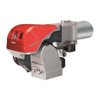
RL 28
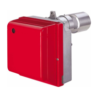
RL 38
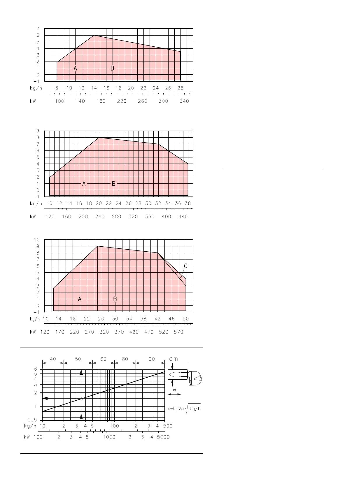
RL 50
D453
D454
pressure mbar
Combustion chamber
pressure mbar
Combustion chamber
pressure mbar
Combustion chamberCombustion chamber
length m
4
FIRING RATES (A)
The RL 28 - 38 - 50 Model burners can work in
two w
ays: one-stage and two-stage.
1st stage DELIVERY
must be selected within
area A of the adjacent diagrams.
2nd stage DELIVERY must
be selected within
area B (and C for model RL 50). This area pro-
vides the maximum delivery of the burner in
relation
to the pressure in the combustion cham-
ber.
The work point may be found by plotting a verti-
cal line from the desired delivery and a horizon-
tal line from the pressure in the combustion
chamber.
The intersection of these two lines is
the work point which must lie within area B.
In order to utilize also area C (RL 50) it is neces-
sary to perform the calibration of the combustion
head as explained
on page 5.
Important
The FIRING RATE area values have been ob-
tained considering a surrounding temperature of
20
°C, and an atmospheric pressure of 1000
mbar (approx. 100 m above sea level) and with
the combustion head adjusted as shown on page
6.
TEST BOILER (B)
The firing rate was set in relation to special test
boilers in accordance with the methods defined
in EN 267 standards.
Figure (B) indicates the diameter and length of
the test combustion
chamber.
Example:
delivery 35 kg/hour:
diameter = 50 cm; length = 1,5 m.
Whenever the burner is operated in a much
smaller
commercially-available combustion
chamber, a preliminary test should be per-
formed.