(A)
(C)
COMBUSTION HEAD SETTING
(F)
(E)
Notches nr.
Light oil delivery kg/h
(D)
(B)
D458
D590
D460
D461
D462
D463
6
Example with RL 38
Boiler output = 270 kW - efficiency 90 %
Output required by the burner =
270 : 0,9 = 300 kW
300 : 2 = 150 kW per nozzle
therefore, two equal, 60°, 12 bar nozzles are
req
uired:
1° = 3,00 GPH - 2° = 3,00 GPH,
or the following two different nozzles:
1° = 2,50 GPH - 2° = 3,50 GPH,
or:
1° = 3,50 GPH - 2° = 2,50 GPH.
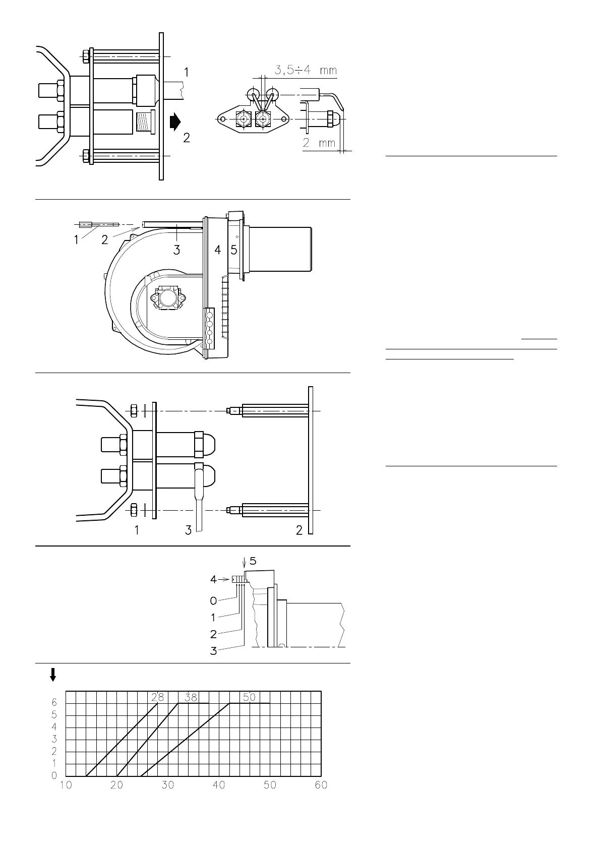
NOZZLE ASSEMBLY
At this stage of installation the burner is still dis-
assembled from the blast tube; it is therefore
possible
to fit two nozzles with the box spanner
1)(A) (16 mm), after having removed the plastic
plugs 2)(A), fitting the spanner through the cen-
tral hole in the flame stability disk. Do not use any
sealing
products such as gaskets, sealing com-
pound, or tape. Be careful to avoid damaging the
nozzle
sealing seat. The nozzles must be
screwed into place tightly but not to the maxi-
mum torque value provided by the wrench.
The nozzle for the 1st stage of operation is the
one lying be
neath the firing electrodes fig. (B).
Make sure that the electrodes are positioned as
shown in fig. (B).
Finally remount the burner 4)(C) to the slide bars
3)
and slide it up to the flange 5),
keeping it
slightly raised to prevent the flame stability disk
from pressing against the blast tube.
Tighten the screws 2) on the slide bars 3) and
scr
ew 1) that attaches the burner to the flange.
If it proves necessary to change a nozzle with the
bur
ner already fitted to the boiler, proceed as
outlined below:
- Retract the burner on its slide bars as shown
in fig. (B)p.5.
- Remove the nuts 1)(D) and the disk 2).
- Use spanner 3)(D) to change the nozzles.
COMBUSTION HEAD SETTING
The setting of the combustion head depends
exclusively on the delivery of the burner in the
2nd stage - in other words, the combined deliv-
ery of the two nozzles selected on page 6.
Turn screw 4)(E) until the notch shown in dia-
gram (F) is level with the front surface of flange
5)(
E).
Example:
The RL 38 Model with two 3.00 GPH nozzles
and 12
bar pump pressure.
Find the delivery of the two 3.00 GPH nozzles in
table (D
), page 5:
12,7 + 12,7 = 25,4 kg/h.
Diagram (F) indicates that for a delivery of 25.4
kg/h
the RL 38 model requires the combustion
head to be set to approx. three notches, as
shown in fig. (E).