20063732
10
Technical description of the burner
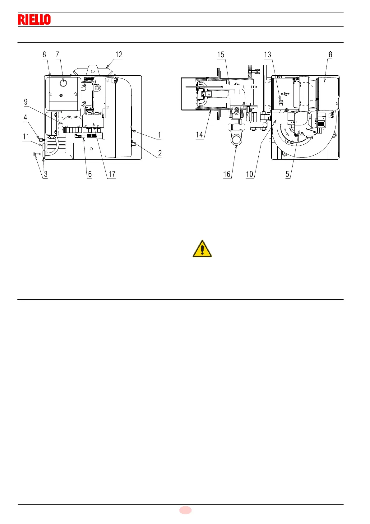
4.8 Burner description
1 Air damper
2 Damper fixing screws
3 Pressure test point (-)
4 Cover fixing screw
5 Air pressure switch
6 Motor
7 Lock-out signal with reset button
8 Control box
9 6 pole socket for gas train
10 Capacitor
11 Grommet
12 Flange
13 Pressure test point (+)
14 Combustion head
15 Electrode-probe
16 Gas train elbow
17 7-pole socket for power supply and remote controls
4.9 Burner equipment
Flange screws and nuts for boiler fixing . . . . . . . . . . . . . No. 4
Insulating gasket . . . . . . . . . . . . . . . . . . . . . . . . . . . . . . . . No. 1
Cover fixing screw . . . . . . . . . . . . . . . . . . . . . . . . . . . . . . . No. 3
Cable grommet. . . . . . . . . . . . . . . . . . . . . . . . . . . . . . . . . . No. 1
Hinge . . . . . . . . . . . . . . . . . . . . . . . . . . . . . . . . . . . . . . . . . No. 1
7-pin plug . . . . . . . . . . . . . . . . . . . . . . . . . . . . . . . . . . . . . . No. 1
Instructions. . . . . . . . . . . . . . . . . . . . . . . . . . . . . . . . . . . . . No. 7
Spare parts list . . . . . . . . . . . . . . . . . . . . . . . . . . . . . . . . . . No. 2
The cable grommet, supplied as standard, should
be assembled on the same part as the gas train.
Check that it is possible to access the cover fixing
screws once the burner has been installed. If nec-
essary, replace them with the ones supplied as
standard.