20063732
14
Installation
5.6 Securing the burner to the boiler
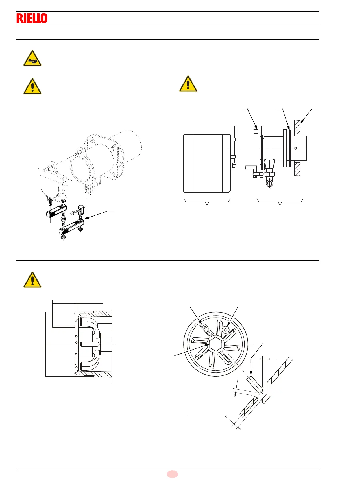
5.6.1 Hinge installation
Install the hinge 4), supplied as standard, as shown in Fig. 8.
Separate the combustion head assembly from the burner
body by removing nut 1) and removing the group A)(Fig. 9).
Fix the group B)(Fig. 9) to the boiler plate 2), inserting the
supplied insulating gasket 3).
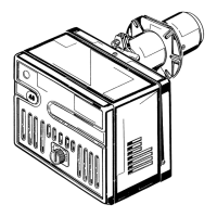
5.7 Positioning the probe - electrode
Provide an adequate lifting system of the burner.
Boiler door must have a max. thickness of 90 mm,
refractory lining included. If the thickness is great-
er (max. 150 mm) a combustion head extension
should be used, to be requested separately.
The seal between burner and boiler must be
airtight.
Respect the positions shown in Fig. 10.
Fig. 10
D5104
Electrode
Diffuser
2.0 - 3.0 mm
Probe
Electrode
2.2
~ 40 mm
=
=
Probe