19
20063732
Installation
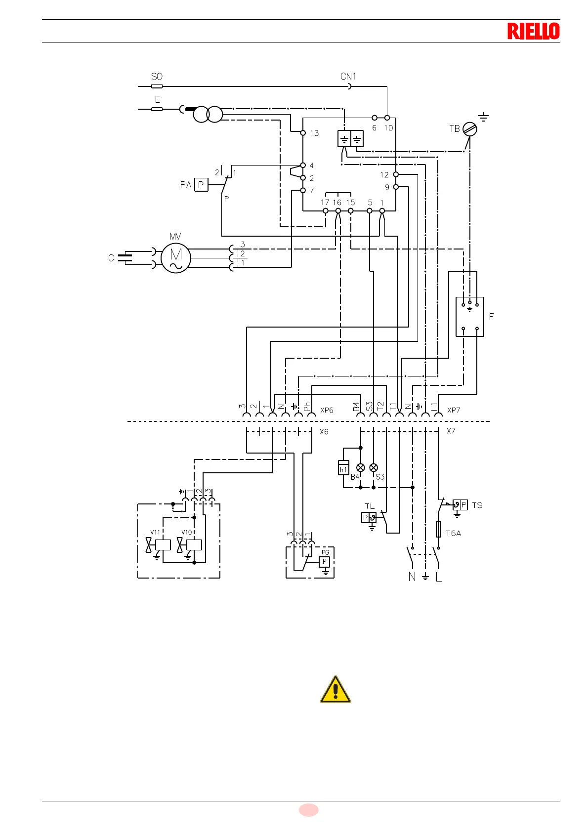
5.11.2 Standard wiring diagram
Key (Fig. 16)
B4 Operating signal
C Motor capacitor
CN1 Ionisation probe connector
E Ignition electrode
FFilter
h1 Hour counter (230V - 0.1A max.)
MV Fan motor
PA Air pressure switch
PG Min. gas pressure switch
S3 Lamp block (230V - 0.5A max.)
SO Ionisation probe
TA Ignition transformer
TB Burner earth
TL Limit thermostat
TS Safety thermostat
T6A Fuse
V10 Safety valve
V11 Adjustment valve
XP6 6- pole socket
XP7 7-pole socket
X6 6 pin plug
X7 7 pin plug
Fig. 16
20066045
RMG88.62C2
In the event of phase-phase power supply, a
bridge should be installed on the terminal board of
the control box between clamp 6 and the earth
clamp.