23
20063732
Start-up, calibration and operation of the burner
6.5 Operation sequence of the burner
6.5.1 Start-up programme visual diagnostics
When operating normally, the various operating statuses can be
see on the control box's LED (reset button) indicated in the form
of a colour code (Tab. G).
Tab. G
6.5.2 Normal operation / flame detection time
The control box has a function through which it is possible to as-
certain the correct functioning of the burner (signal: GREEN LED
permanently on).
To use this function, it is necessary to wait at least 10s. from the
time the burner switches on and press the button on the control
box for at least 3 seconds.
Once the button is released, the GREEN LED starts to flash, as
shown in Tab. H.
The pulses of the LED constitute a signal spaced by approxi-
mately 3 seconds.
The number of pulses will measure the probe detection time
since the opening of gas valves, according to: Tab. I.
This is updated in every burner start-up.
Once read, the burner repeats the start-up cycle by briefly press-
ing the control box button.
Tab. H
Tab. I
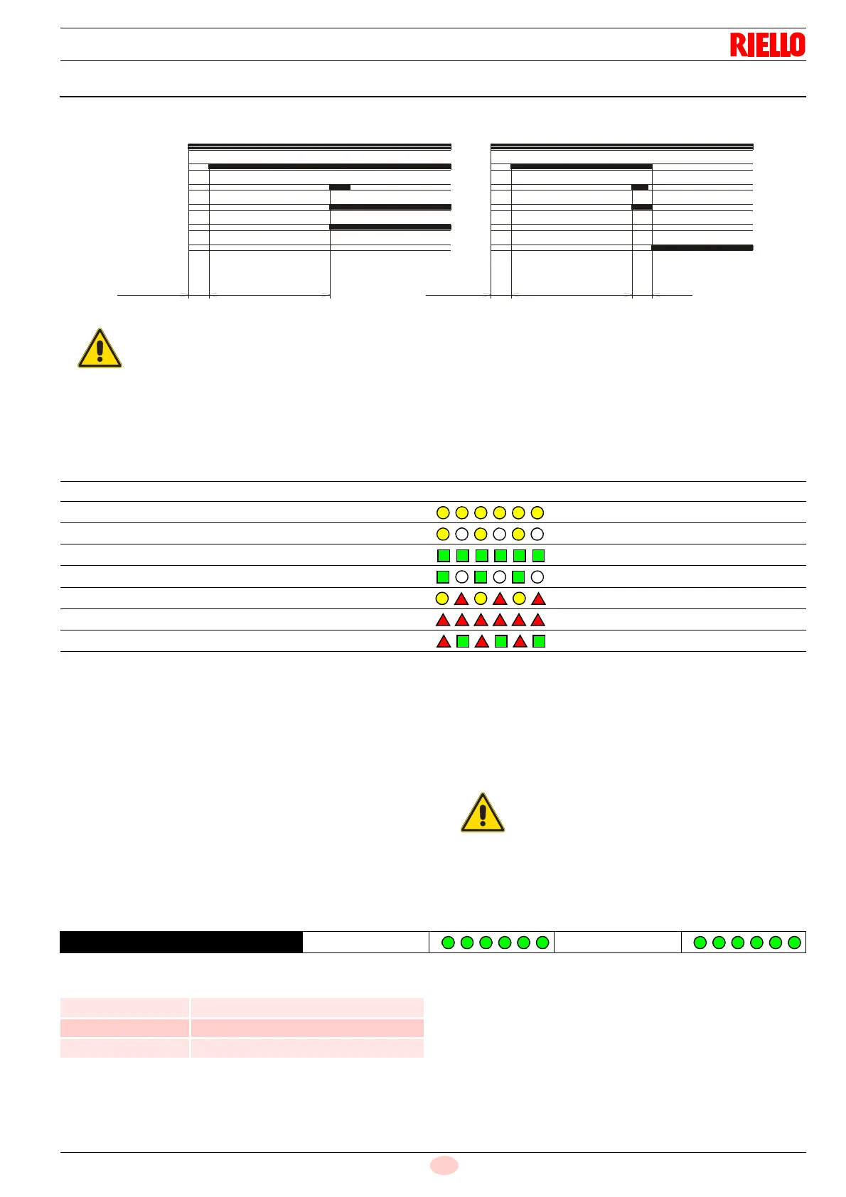
Thermostat
Motor
Ignition transformer
Valves
Flame
Lockout
3s40s40smax. 2s max. 2s
D4172
Lockout due to ignition failureNormal
Fig. 20
If the flame goes out while running, the burner
goes into lockout within 1 second.
Sequences Colour code Colour
Pre-purge Yellow
Ignition phase Yellow - Off
Operation, flame OK Green
Operation with weak flame signal Green - On
Electrical supply below ~ 170V Yellow - Red
Lockout Red
Extraneous light Red - Green
If the result is > 2 s, ignition will be retarded. Then
check the adjustment of the hydraulic brake on the
gas valve, the adjustment of the air damper and
the combustion head.
GREEN LED ON
wait at least 10s
Press the button
for > 3s
Signal
3s interval
Signal
Signal Flame detection time
1 blink 0.4 s
2 blinks 0.8 s
6 blinks 2.8 s