20160576
10
Technical description of the burner
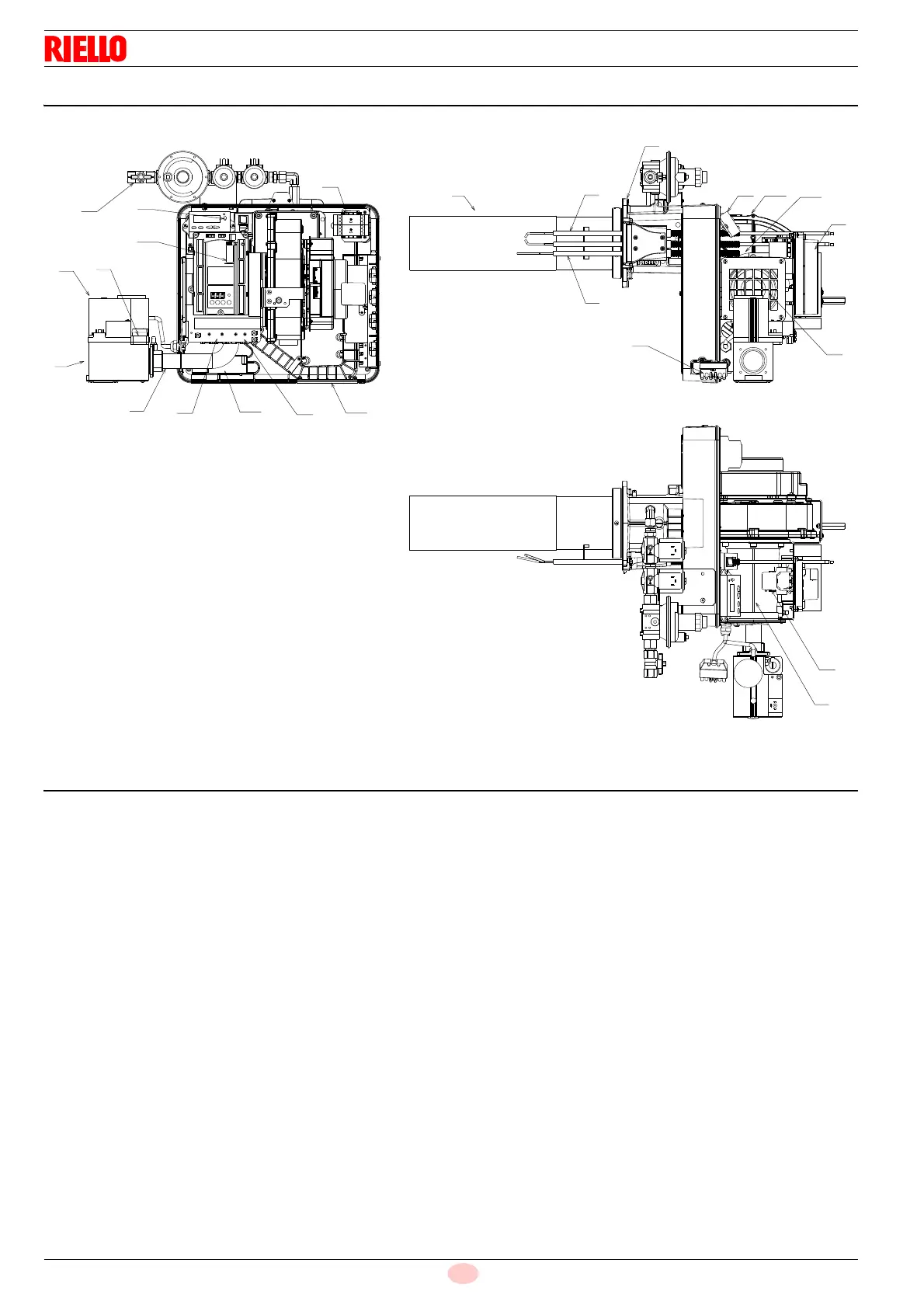
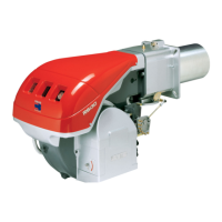
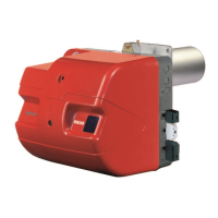
4.7 Burner description
4.8 Combustion head
1 Ignition electrode
2 Flame sensor probe
3 Gas valve
4 Air/gas mixer in the suction line circuit
5 Gas pressure test point
6 Gas valve conduit - Venturi
7 Gas input
8 Boiler fixing flange
9Fan
10 Air passage in fan
11 Control box
12 Programming card
13 Plug-socket on ionisation probe cable
14 Gas train pilot
15 Transformer
16 Plate with four hole knock-outs for electrical cable routing
17 Reset button
18 7 pin plug
19 Fuses
20 4 pin plug
21 6 pin plug
22 Display
23 Timers
Burner lockout may occur.
control box lockout:
if the control box 13)(Fig. 3) push-button lights up, it indicates
that the burner is in lockout.to reset, press the push-button.