20160576
26
Installation
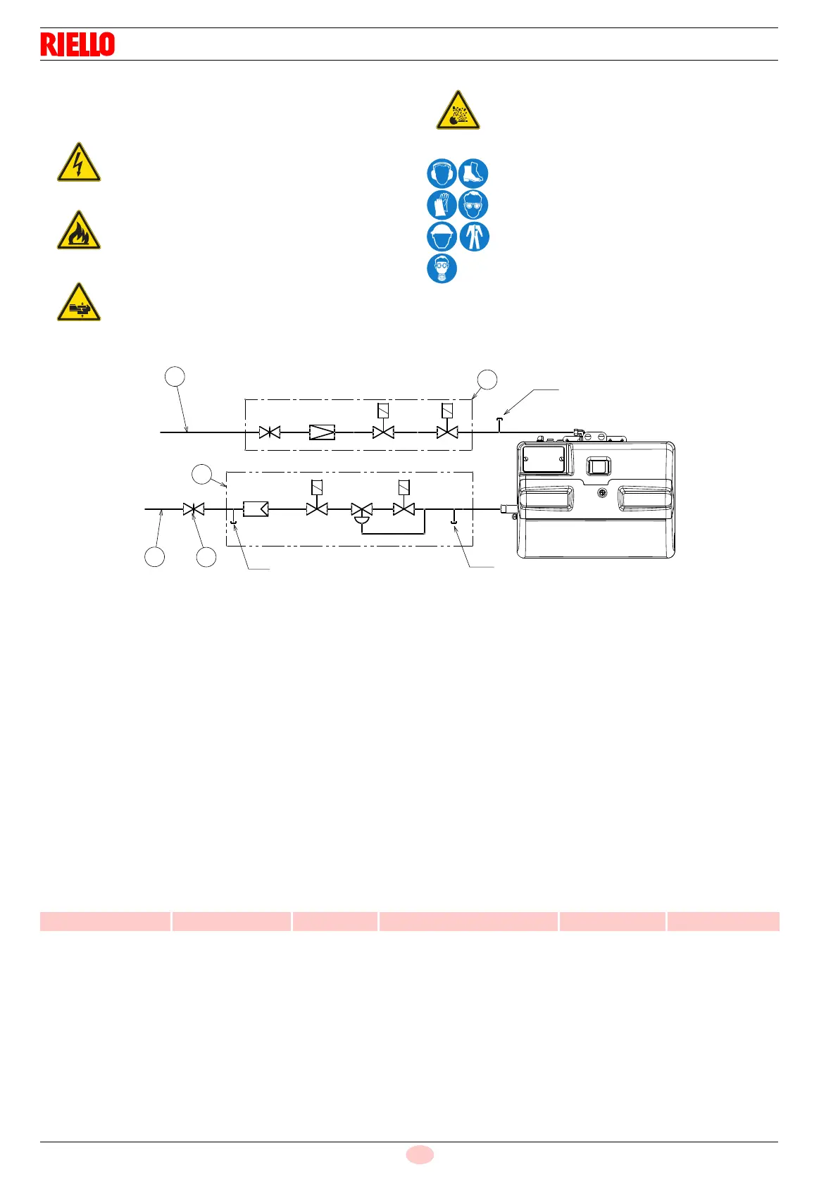
5.8.2 Gas train
This has been type-approved together with the burner, in accord-
ance with regulation EN 676, and is supplied as standard.
Key (Fig. 23)
1 Gas input pipe
2 Manual valve
3 Valve including:
- filter (replaceable) (F)
- working valves (V1 - V2)
- pressure adjuster (R)
4 Pilot valve including:
- manual valve (VM)
- pressure adjuster (PR)
- safety valves (VP1 - VP2)
P1 Pressure upline of the filter
P2 Downstream pressure of valve
P3 Downstream pressure of pilot
Tab. N
Disconnect the electrical power using the main
switch.
Check that there are no gas leaks.
Pay attention when handling the train: danger of
crushing of limbs.
Make sure that the gas train is properly installed
by checking for any fuel leaks.
The operator must use the required equipment
during installation.
V1
V2
R
F
1
2
3
P1
P2
VP1
1
PR
VP2
P3
4
VM
GAS TRAINS MAXIMUM INLET
PRESSURE
BURNER
MODEL IN OUT mbar MODEL USE
VR 420 VA 1004 1” 1” 100 RX 180-250 S/PV G20 - G25 - GPL