33
COMMISSIONING
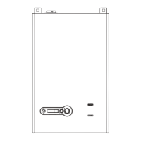
− CH Mode 1 - Room Themostat & Outdoor Reset: this
mode requires an outdoor sensor, in addition to the room
thermostat. The system functions similar to CH mode
0, except the Tempererature Setpoint is automatically
calculated based on the Reset curve. Curve parameters are
available on the Reset curve screen (through the Settings
screen).
Fig. 47
Reset Curve screen
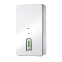
By adjusting the parameters on the screen, the reset curve will
modify its shape and sloper to meet the needs of the specic
application (see Fig. 48).
20
OUTDOOR TEMP. (°C/°F)
Reset Curve
Design Boiler
93
Reset Curve
Outdoor Design
1) Reset Curve Outdoor Mild Weather
2) Warm Weather Shutdown
Reset Cuve
Boiler Mild
Weather
Reset Curve Boiler
Maximum
200
82 180
71 160
60 140
12049
10038
27 80
60
16
°C °F
-6
40
4
60
16
80
27
100
38
°F
°C
Reset Curve Boiler
Minimum
CH SETPOINT (°C/°F)
Fig. 48
Reset Curve
− CH Mode 2 - Full Outdoor Reset: just an outdoor sensor
is required. The Temperature Setpoint is still automatically
calculated based on the Reset curve. If a room thermostat
is installed, it activates the Night setback function (setpoint
reduction during the night) but it does not affect the CH
demand.
− CH Mode 3 - Permanent Demand: the system works
similarly to Mode 0. Supply temperature is kept at the
Setpoint level steadily. If a room thermostat is installed,
it activates the Night setback function (setpoint reduction
during the night) but it does not affect the CH demand.
Module pump is always ON.
− CH Mode 4 - Analog Input to Setpoint: the Temperature
Setpoint is given by an analog signal provided by a remote
control such as a Building Management System or a system
controller. A heat demand will be generated by an input of
1.5 Volts or higher. Modulation will occur between 2 and 9
Volts. Voltage below 1 Volt will shutoff any demand.
−
NOTE: after selecting CH mode 4, enable it either:
−
jumpering “Enable/Disable” pins (#11-12) on Terminal strip
(see Fig. 24)
or
−
accessing the list of parameters through the Service display
and move parameter #124 from 1 (default value) to 0.
CH Setpoint
Maximum
CH Setpoint
Minimum
1.51.0 2.0 9
Voltage
OFF ONON/OFF
Hysterese
OFF
ON
Modulating
Fig. 49
10VDC Control mode
NOTE: Scale the analogue signal to match the system
temperature requirements. scaling the temperature
range using the boiler parameters will articially limit the
maximum operating temperature of the boiler.
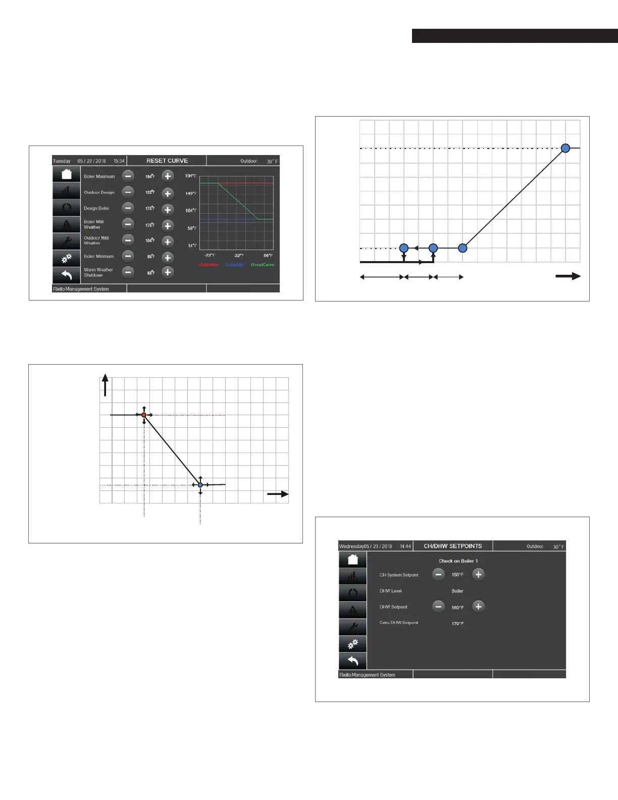
Domestic Hot Water (DHW) function can be enabled using the
parameter 35 on Service display.
Three modes are available:
− DHW mode 0 - DHW function disabled.
− DHW mode 1 - Tank with sensor: hot water is stored in
a tank where the temperature is measured by a sensor.
Either a pump or a 3-way valve can be used to switch to
DHW mode. When the DHW demand is on, the boiler is PID
modulated to achieve the supply temperature made by
the DHW store setpoint increased by an adjustable extra
temperature. DHW store setpoint is manually set on the CH/
DHW Setpoints screen (through the Settings screen).
Fig. 50
CH/DHW Setpoints
− DHW mode 2 - Tank with thermostat: hot water is stored in
a tank where the temperature is detected by a thermostat
(ON/OFF signal). Either a pump or a 3-way valve can be used
to switch to DHW mode. When the DHW demand is on, the