3004
5
GB
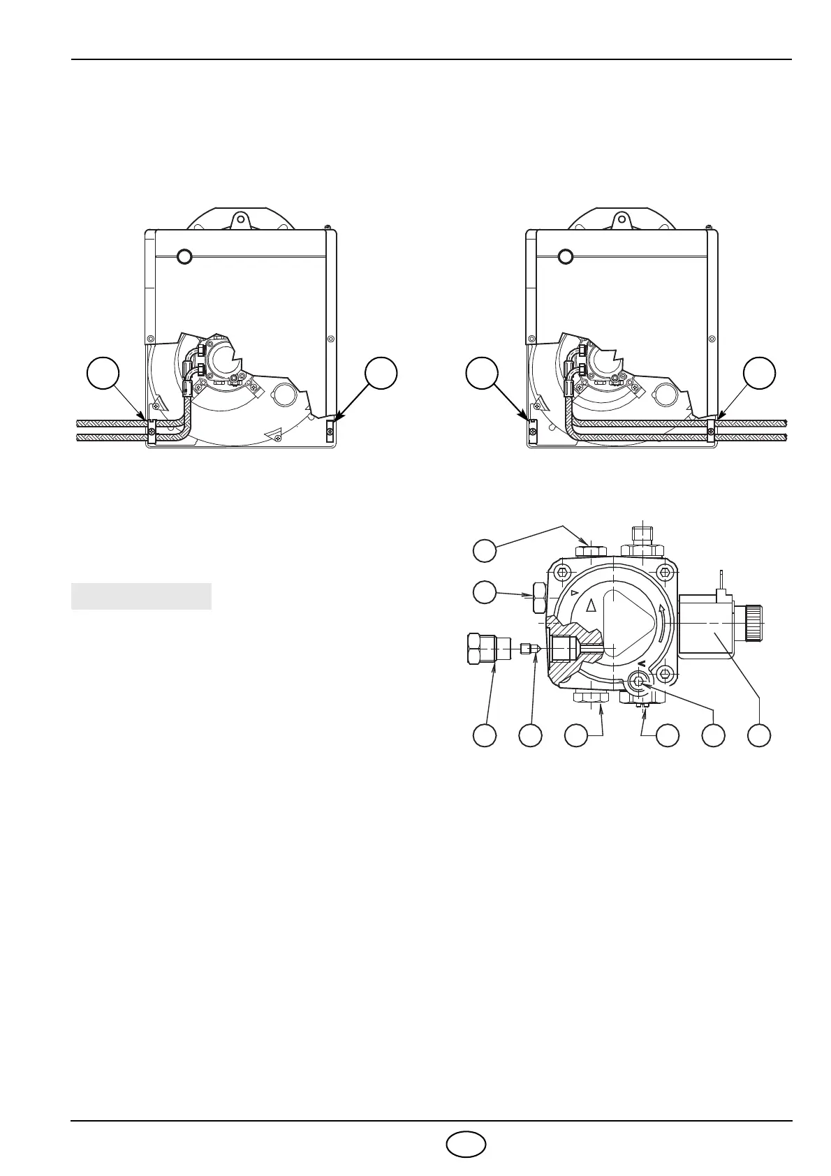
3.3 FUEL SUPPLY
The burner is designed to allow entry of the oil supply pipes on either side.
Depending on the oil supply pipes position (to the right or to
the left hand side of the burner) the fixing plate
(1) and closing plate (2) should be reversed, (see Fig. 5).
3.4 HYDRAULIC SYSTEMS
1 - Suction line
2 - Return line
3 - By-pass screw
4 - Gauge connection
5 - Pressure adjuster
6 - Suction gauge connection
7 - Valve
8 - Auxiliary pressure gauge
Fig. 6
1
2
3
4567
8
D5026
y
It is necessary to install a filter on the fuel supply
line.
O
The pump is designed to allow working with two
pipes
.
O In order to obtain one pipe working it is necessary to
unscrew the return plug (2), remove the by-pass
screw (3) and then screw again the plug (2) with a
torque of 0.5 Nm.
O
Before starting the burner make sure that the return
pipe-line is not clogged. An excessive back pressure
(
Š 1 bar) would cause the damage of the pump seal,
with subsequent fuel leaks inside the burner.
The pump has a delivery pressure regulation device (4).
Pre
ssure increases if turned in a clockwise direction,
and decreases if turned in the other direction.
An indication of sensitivity is 1 bar per turn.
The pressure can be regulated in a range of 8 - 15 bar.