9
20136874
Technical description of the burner
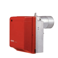
4.6 Maximum dimensions
The maximum dimensions of the flange and burner are given in Fig. 1.
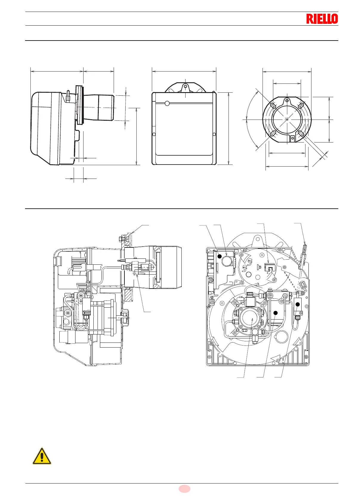
4.7 Burner description
1 Oil pump
2 Control box
3 Reset button with lock-out signal
4 Flange with insulating gasket
5 Air damper adjustment assembly
6 Nozzle-holder assembly
7 Flame sensor
8 Hydraulic jack
9 Delaying device
Fig. 1
228 142 300
213
160
190
12
36
285
345
11
9999
127
4
5
°
4
5
°
D5353
ø 123
To meet the required standards, the burner must
be protected by a pane or by the boiler door.
This protection must be removed only with a tool.