19
20136874
Start-up, calibration and operation of the burner
6.1 Notes on safety for the first start-up
6.2 Combustion adjustment
In conformity with EN 267, the installation of the burner on the
boiler, the adjustment and testing must be carried out in compli-
ance with the instruction manual of the boiler, including control of
the CO and CO
2
concentration in the flue gases, their tempera-
ture and the average temperature of the water in the boiler.
To suit the required boiler output, choose the nozzle, the pump
pressure and the adjustment of the air damper according to the
following table.
The values in Tab. G refer to 12.5% of CO
2
at sea level, and
with a light oil and ambient temperature of 20°C.
Tab. G
6.3 Recommended nozzles
The burner complies with the emission requirements of the EN
267 standard. In order to guarantee that emissions do not vary,
recommended and/or alternative nozzles specified by manufac-
turer in the Instruction and warning booklet should be used.
Steinen type S - SS
Danfoss type S - B
Delavan type B - W
Monarch type R
6 Start-up, calibration and operation of the burner
The first start-up of the burner must be carried out
by qualified personnel, as indicated in this manual
and in compliance with the standards and regula-
tions of the laws in force.
Check the correct working of the adjustment, com-
mand and safety devices.
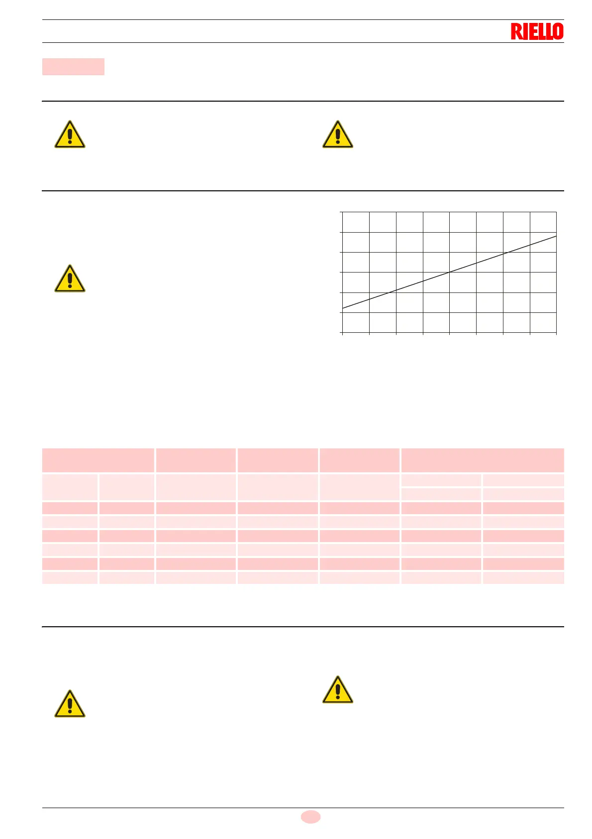
The temperature of the combustion air (relative to
the place where the burner is installed) may vary
during the season, it influences the CO
2
of the
burner.
We recommend adjusting the CO
2
based
upon the temperature of the combustion air at the
time when the burner calibration is carried out in
accordance with what is shown in the following di-
agram.
E.g. with combustion air temperature of 10°C, ad-
just the CO
2
to 12.5%.
% CO
2
External air temperature (°C)
14.5
14.0
13.5
13.0
12.5
12.0
11.5
0 5 10 15 20 25 30 35 40
D4604
Fig. 18
Nozzle
Pump
Pressure
Burner
output
Combustion head
adjustment
Air damper
adjustment
GPH Angle bar kg/h ± 4% Set-point
Low flame High flame
Set-point Set-point
2.50 60° 12 10.0 0 0.2 1.4
3.00 60° 12 12.0 1 0.4 2.1
3.50 60° 12 14.0 2.5 0.7 3.0
4.00 60° 12 16.1 4 0.9 3.5
4.50 60° 12 18.1 6 1.4 4.5
4.50 60° 14 19.5 6 1.4 6.0
It is advisable to replace nozzles every year dur-
ing regular maintenance operations.
The use of nozzles other than those specified by
manufacturer and inadequate regular mainte-
nance may result into emission limits non-con-
forming to the values set forth by the regulations
in force, and in extremely serious cases, into po-
tential hazards to people and objects.
The manufacturing company shall not be liable for
any such damage arising from non-observance of
the requirements contained in this manual.