20136874
18
Installation
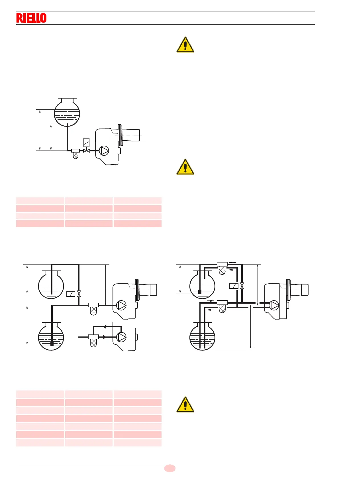
5.11.4 Pressurised one-pipe systems
Pressurised one-pipe systems (Fig. 16) have a positive fuel pres-
sure on intake to the burner.
Usually the tank is higher than the burner, or the fuel pumping
systems are on the outside of the boiler.
In order to obtain one pipe working it is necessary to unscrew the
return line plug 2)(Fig. 15), remove the by-pass screw 3)(Fig. 15)
and then screw the plug 2)(Fig. 15) in again at a tightening torque
of 0.5 Nm.
Tab. E
H = Difference of level
L = Maximum suction line length
Ø = Inner diameter of the pipe
In the systems in Fig. 16 and Fig. 17, the table shows the maxi-
mum approximate lengths for the supply line, depending on the
difference in level, length, and the diameter of the fuel conduit.
5.11.5 Priming pump
In the system of Fig. 16 just loosen the connection of the vacuom-
eter 5) (Fig. 15) and wait for the fuel to come out.
In the systems A and B of Fig. 17 start the burner and wait for the
priming. Should lockout occur prior to the arrival of the fuel, await
at least 20 seconds before repeating the operation.
The pump vacuum should not exceed a maximum of 0.4 bar (30
cm Hg).
Beyond this limit gas is released from the oil.
5.11.6 Vacuum systems
Depressurised systems (Fig. 17) have a negative fuel pressure
(depression) at the burner intake.
Usually the tank is lower than the burner.
Tab. F
H = Difference of level
L = Maximum suction line length
Ø = Inner diameter of the pipe
H
metres
L metres
Ø (8 mm) Ø (10 mm)
0.5 10 20
1 20 40
1.5 40 80
2 60 100
The installer must ensure that the power supply
pressure never exceeds 0.4 bar (30 cm Hg).
Above that level, the pump seal is subject to too
much stress.
The pipes must all be perfectly sealed.
Fig. 17
H
max. 4 m
max. 4 m
H
H
H
D5337
H
metres
L metres
Øi
8 mm
Øi
10 mm
0 35 100
0.5 30 100
1 25 100
1.5 20 90
2 15 70
3 8 30
3.5 6 20
The installer must ensure that the supply de-
pression never exceeds 0.4 bar (30 cm Hg).
Beyond this limit gas is released from the oil.
The pipes must all be perfectly sealed.