15
20136874
Installation
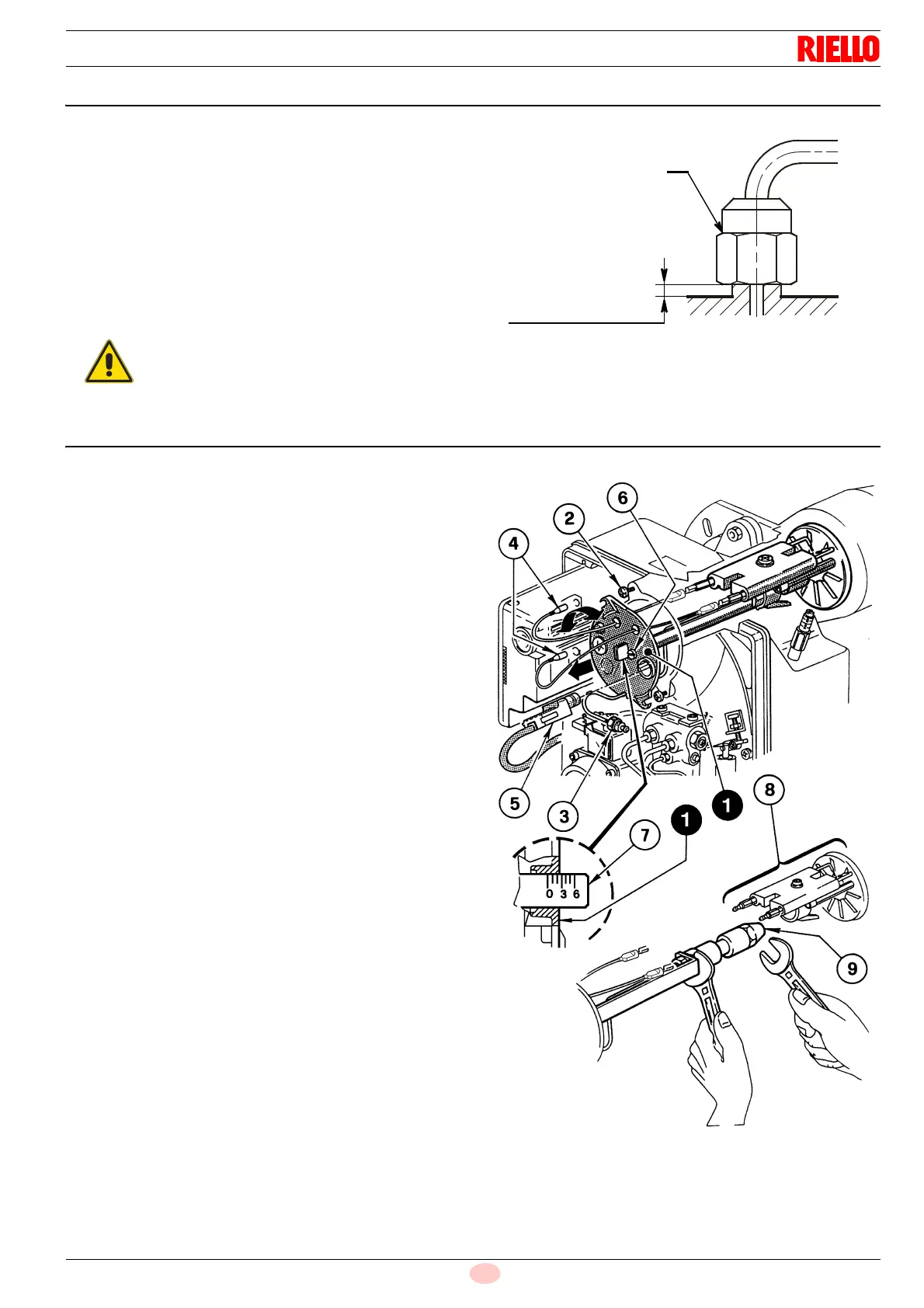
5.7 Maintenance position
For accessing the nozzle, the diffuser disc and the electrodes, fol-
low the instructions below:
take out the nozzle-holder assembly 1)(Fig. 11) after loosen-
ing the screws 2)(Fig. 11), having unscrews the nuts 3)(Fig.
11), removed the wires 4)(Fig. 11) from the control box and
the flame sensor 5)(Fig. 11).
Take out the wires 4)(Fig. 11) from the electrodes, remove
the nozzle-holder assembly 1)(Fig. 11) the diffuser disc-
holder assembly 8)(Fig. 11) after loosening the screw
3)(Fig. 13).
Screw in the nozzle 9)(Fig. 11) tightening it correctly as
shown in Fig. 11.
5.8 Combustion head adjustment
The adjustment of the combustion head varies depending on the
burner output.
Do the following to adjust it:
turn the adjustment screw 6)(Fig. 11) clockwise or anti-clock-
wise until the notch on the regulating rod 7)(Fig. 11) lines up
with the outer surface of the nozzle-holder assembly 1)(Fig.
11).
Example: the head is set for an output of 3.5 GPH at 12 bar.
The notch 2.5 of the regulating rod lines up with the outer surface
of the nozzle-holder assembly as shown in the Tab. G.
Having put back the nozzle-holder assembly,
screw in the nut 9), as shown in Fig. 10.
Fig. 10
D5684
9
Tighten without
bringing right to
the end stop