Rinnai 11 I Series Evap AC IM
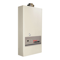
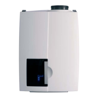
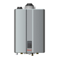
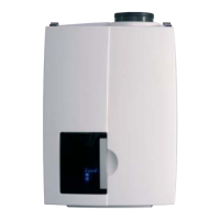
4.1 EVAPORATOR MODULE
The Evaporator Module is where heat transfer through evaporation takes place and this shall be installed within
the roof space� The Evaporator Module contains the Rinnai I Series control system and water distribution system
which supplies water to the cooling pads� This shall be installed on the Safety Tray supplied by Rinnai�
4.2 VENTILATION – FRESH AIR INTAKE
It is the installer’s responsibility to ensure the minimum air intake requirements are met to service the Rinnai I
series Evaporator Module�
The minimum air intake requirement for the I20 model is 0�5 m² open area and for the I10 model is 0�3 m² open
area� This may be achieved with the use of an Roof Cap, Rinnai I Series Eave Vents, roof vents, or gable vents�
The Roof Cap and Rinnai I Series Eave Vents are air intake accessories available from the Rinnai for BAL and non-
BAL installations� The I20 model requires eight (8) Rinnai I Series Eave Vents and the I10 model requires four (4)�
4.3 FIX AND SEAL THE ROOF FLASHING
If you install an Roof Cap refer to the installation instructions
supplied with the Roof Cap and the following guidelines�
The Colorbond™ roof ashing (installer supplied) shall be xed
and sealed to the dropper duct to prevent water entry into the
building�
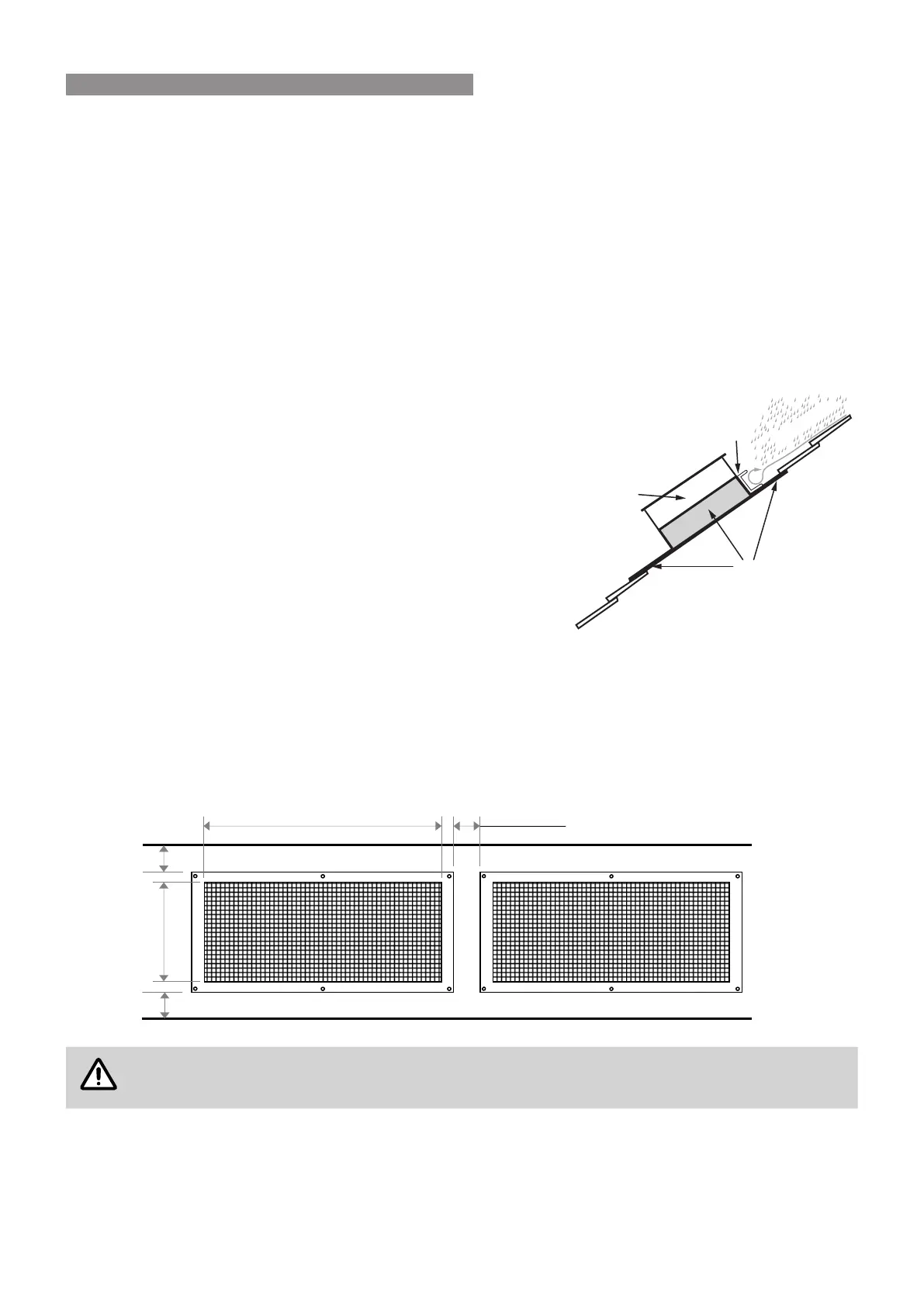
Installations where the Cooler is more than 4 metres downstream
from the roof peak should be tted with an additional water
diverting channel on the dropper duct high side, that extends
beyond the dropper duct sides by at least 50mm (see diagram
right)�
4.4 RINNAI I SERIES EAVE VENT INSTALLATION
Rinnai I Series Eave Vents shall be installed with six fasteners each (installer supplied), which are suitable with the
type of material the eave vents are being secured to�
There should be a minimum distance of 20mm from the outer edge of eave vent to edge of eave material and
between eave vents�
Using dimensions A & B of the eave vent inner border (diagram below), mark out the eave vent location, remove
eave material and secure the eave vent�
Eave vents should be installed between joists where practicable.
Flashing
Water diverter channel
Dropper Duct
Eave edge
4. COOLER HARDWARE
 Loading...