Rinnai 14 I Series Evap AC IM
5.7 COOLING PAD REMOVAL
Prior to removing the Cooling Pads all of the Fan Assemblies must be removed as detailed in section "5�6 Remove
Fan Assemblies" on page 13, up to the end of Step 5�
To remove the Cooling Pads follow the below procedure:
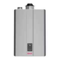
1� Lift the Cooling Pad up 50mm to dislodge from
the water manifold supply spigot at the base of
the pad�
2� Rotate the Cooling Pads away from the centre of
the unit� This is typical for all four Cooling Pads�
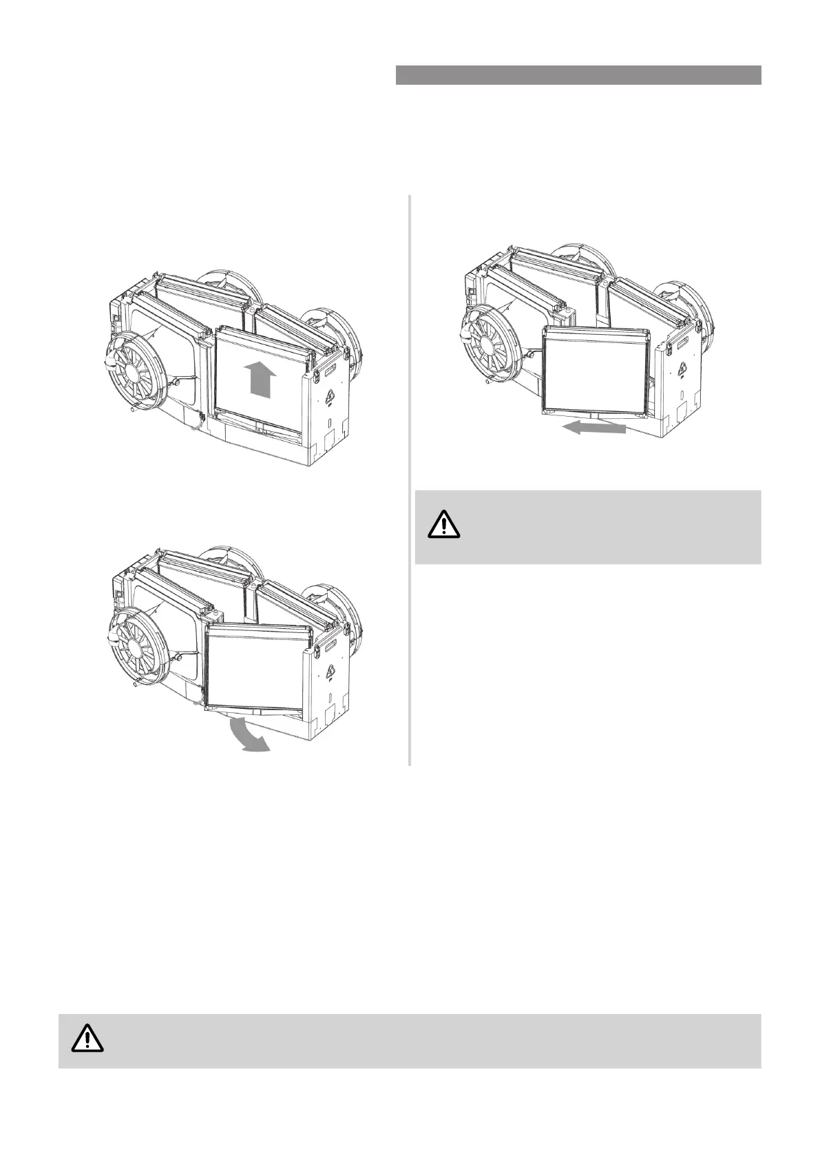
3� Remove Cooling Pad horizontally away from the
unit as shown�
4� To assemble Cooling Pads repeat steps 3 through
to 1 in reverse�
The socket on the Cooling Pad must seat
correctly on the water manifold spigot
to ensure water is delivered to each pad
equally.
To conrm Cooling pads are positioned correctly check
the following:
•
The top of all Cooling pads when in position are at
the same level�
•
The Acoustic Cooling Chamber – Top mates correctly
with the Evaporator Module ends and sides, i�e� no
gaps�
•
Toggle clips t correctly.
5.8 EVAPORATOR MODULE – PRIMARY DRAIN
The drain outlet shall be plumbed to a suitable point in order to disperse the waste water away adequately without
causing damage or nuisance, i.e. no overowing.
Ensure that all installer supplied drainage pipe is rigid (not exible) and UV stabilised if exposed to the external
environment�
Ensure any drain has a continuous fall, the joints and ttings are adequately sealed, and that all penetrations in
and out of the roof cavity are correctly sealed against water entry into the building, i�e� shall be compliant with local
plumbing regulations�
The drain pipe shall also be properly supported along its entire run, and shall not place strain on the Evaporator
Modules outlet tting or base.
The drain connection size at the Evaporator Module is to suit DN20 pressure pipe.
The “Evaporator Module” drain and “Safety Tray” drain shall not be joined.
5. EVAPORATOR MODULE INSTALLATION
 Loading...