Rinnai 12 I Series Evap AC IM
5.1 PRIOR TO INSTALLATION
Ensure to review your local plumbing regulations as you may need to consider either down pipe, storm water pit or
sanitary drain locations when deciding on the position of the Evaporator Module�
5.2 SERVICE LIGHT & ACCESS WALKWAY
•
A service light should be installed adjacent to the unit’s control access panel inside of the ceiling space�
•
The service light switch should be located near the manhole�
•
An access walkway should be installed from the man hole to the Evaporator Module and should be free of
obstruction to allow access for service and maintenance� If rafter pitch is greater than 700mm a walkway shall
be installed to assist with service access�
5.3 EVAPORATOR MODULE LOCATION
Inspect the roof space prior to positioning the Evaporator Module and decide on the best orientation for connection
of plumbing and service access�
A minimum distance of 555 mm is required between adjacent rafters to install the Evaporator
Module.
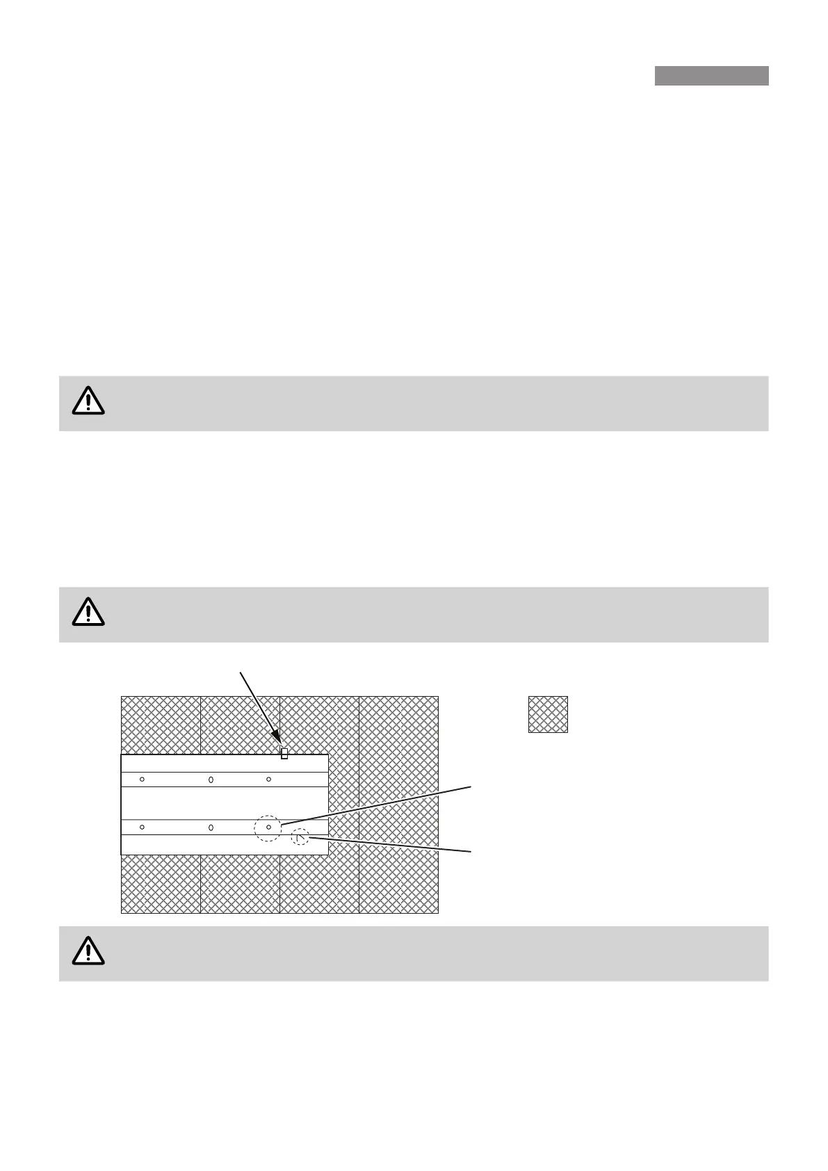
5.4 POSITIONING THE PLATFORM & SAFETY TRAY
For servicing, a working platform shall be provided, capable of supporting a tradesman and his tools� Secure the
platform to the ceiling joists ensuring the position enables the required service clearances between Safety Tray
and the platform edge (refer to diagram below)�
With the Evaporator Module and Safety Tray on the ground remove the Evaporator Module from the Safety Tray
and relocate the Safety Tray to within the roof space� Position the Safety Tray on the boards (as shown in diagram
below) and DO NOT fasten to the platform as puncturing the Safety Tray will damage its functionality�
The controls end for the Evaporator Module shall be located at the same end as the Safety Tray
Drain. There are location holes in the Safety Tray supporting channels to assist with unit location.
6DIHW\7UD\
3ODWIRUP
/RFDWLRQKROHV[LQ³6DIHW\7UD\´
WRSKDWIRU³(YDSRUDWRU0RGXOH´IHHW
&DEOHWLHWRVHFXUHZDWHUVXSSO\
EUDLGHGKRVH
The Rinnai I Series may be raised on the safety tray to ensure the primary and secondary drain
achieve continuous fall.
5.5 POSITIONING THE EVAPORATOR MODULE
A distance between rafters of 555 mm is required to enable installation of the Evaporator Module� Before lifting and
locating to within the roof space the Evaporator Module shall have the fan assemblies removed�
5. EVAPORATOR MODULE INSTALLATION
 Loading...