Rinnai 18 I Series Evap AC IM
6.4 ZONING
All Rinnai I Series models can be congured for zoning, with each zone assigned to a wall control and fan motor(s).
The I20 model is capable of connecting to a maximum of four wall controls and the I10 model a maximum of two
wall controls�
Each zone can be either in “Manual” mode, “Auto” mode, or “OFF”. To operate any zone in “Fan Only” mode all
wall controls that are ON must be in “Fan Only” mode to turn the circulation pump off�
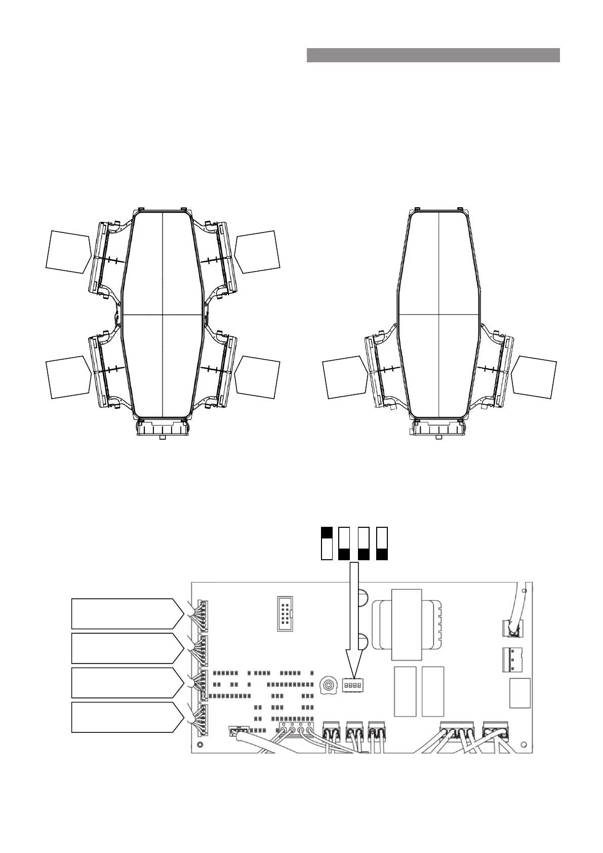
For the I20 and I10 model fan motor congurations, refer to following diagrams.
I20 & I10 model motor conguration
When multiple wall controls are installed for zoning they must be installed in sequential order, refer to the diagram
below for connection information�
Wall Control location on PCB
Fan
Motor
#2
Fan
Motor
#1
Fan
Motor
#4
Fan
Motor
#3
Fan
Motor
#1
Fan
Motor
#2
Dip Switch Number
Wall Control #1
Connection
Wall Control #3
Connection
Wall Control #4
Connection
Wall Control #2
Connection
6. WALL CONTROL LOCATION & MOUNTING
 Loading...