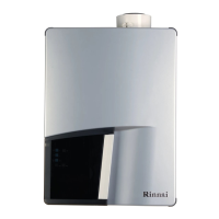
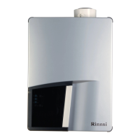
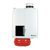
Rinnai 19 I Series Evap AC IM
When multiple wall controls are installed for zoning the “Dip Switch Position” on the control board must change,
refer to Tables 2 & 3�
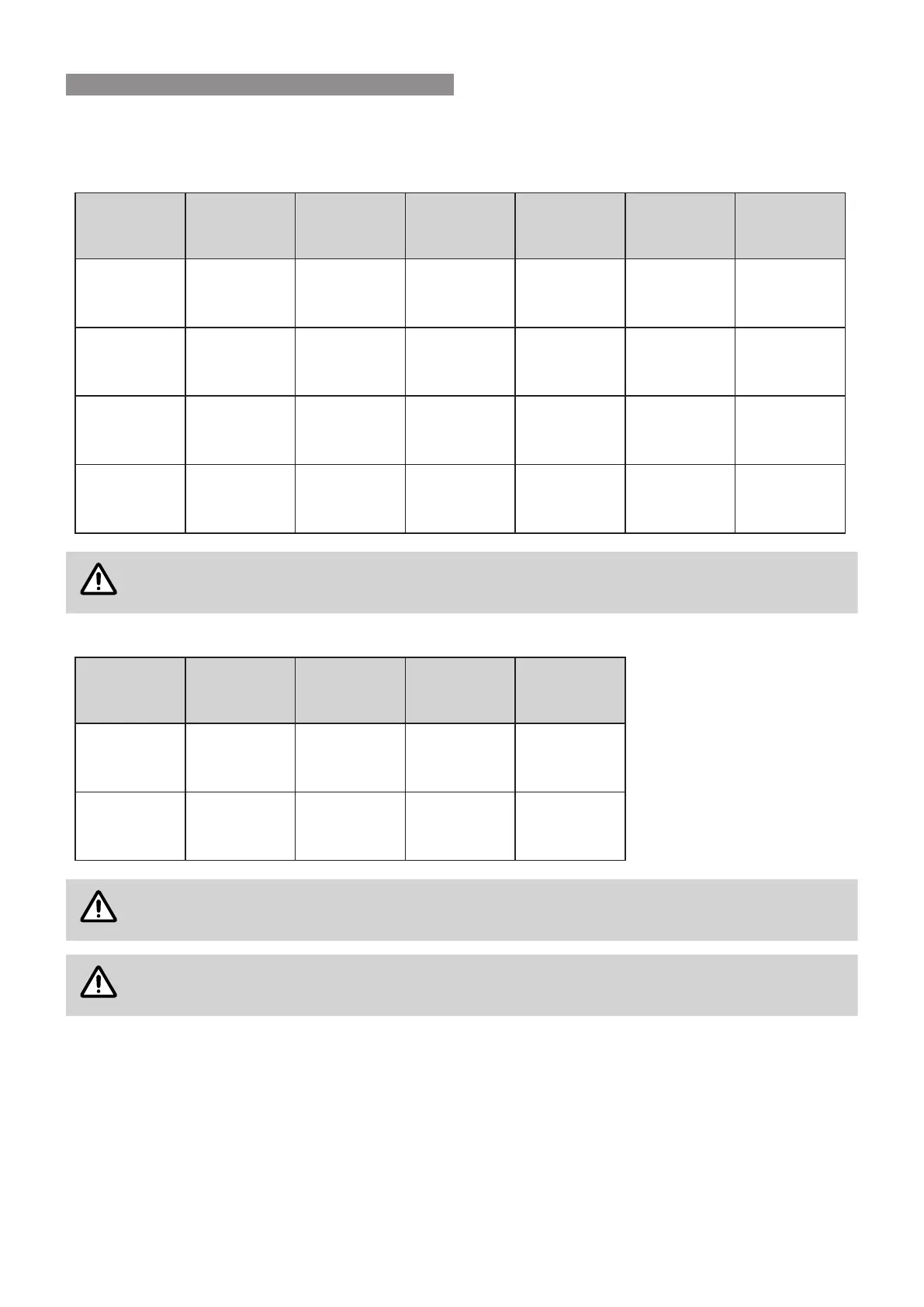
Table 2� I20 model Dip Switch Position for 1 to 4 wall controls�
Dip Switch
Position
Number of
Wall Controls
Zone
Detail
Zone A Zone B Zone C Zone D
1-0-0-0
(Default)
1
Common
Zone
Fans
1, 2, 3 & 4
N/A N/A N/A
1-1-0-0 2
Two Zones
A & B
Fans
1 & 2
Fans
3 & 4
N/A N/A
1-1-1-0 3
Three Zones
A, B & C
Fan
1
Fan
2
Fans
3 & 4
N/A
1-1-1-1 4
Four Zones
A, B, C & D
Fan
1
Fan
2
Fan
3
Fan
4
Dip Switch Up is ‘1’ and Dip Switch Down is ‘0’
Table 3� I10 model Dip Switch Position for 1 to 2 wall controls�
Dip Switch
Position
Number of
Wall Controls
Zone
Detail
Zone A Zone B
1-0-0-0
(Default)
1
Common
Zone
Fans
1 & 2
N/A
1-1-1-1 2
Two Zones
A & B
Fan
1
Fan
2
Dip Switch Up is ‘1’ and Dip Switch Down is ‘0’
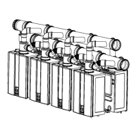
Rinnai I Series Coolers comes supplied with one wall control loom connected to “Wall Control
#1 Connection”.
6. WALL CONTROL LOCATION & MOUNTING
 Loading...