Rinnai 23 HW_HD_CF OIM
The REU-E series water heaters (Innity Enviro 16 and Innity Enviro 26) generate condensate continuously at a
rate of up to 5 litres per hour as a by-product of highly ecient gas burner system.
This condensate has been neutralised by pre-tted Condensate Neutraliser Kit.
The conguration of drain lines MUST be in accordance with local regulatory requirements and the requirements
of AS/NZS3500.4.
IMPORTANT CONSIDERATIONS FOR NEUTRALISER DRAIN PIPE
The content of AS/NZS 3500 ‘Temperature / Pressure Relief and Expansion Control Valve Drain
Lines’ has been used as a guide in preparing these considerations.
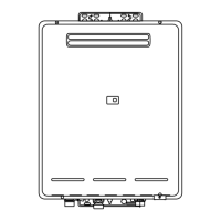
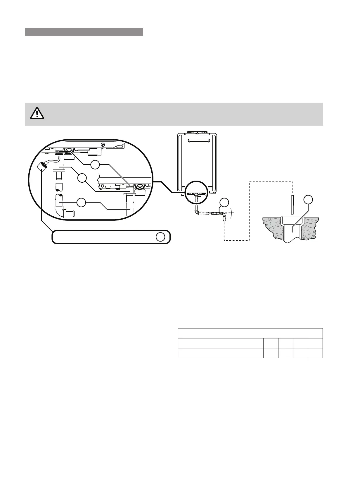
A
Water heater drain outlet connection, R½” (15 mm) BSP male. Condensate / Neutraliser drain outlet
connection, 1/2” (15mm) BSP male nylon (Note: the black plastic shipping cap MUST BE removed from the
condensate / neutraliser drain outlet prior to water heater operation).
B
PE R½” BSP (15 mm) female to barbed irrigation system connector (13 – 19mm) or equivalent plastic tting.
C
Drain pipe and ttings to match item
B
.
D
Continuous fall (of at least 2°) from water heater to discharge point. Lengths and bends in accordance with
‘Length & Changes Of Direction’ table below.
E
Suitable points of discharge are deemed to be drains, sewers or pits. DO NOT discharge onto electrical
connections, earth stakes, copper pipes, concrete paths or into a pond.
Length & Changes Of Direction
Maximum length and changes of direction greater than
45° should be as follows:
Lengths and changes of direction
Max length (Metres) 9 8 7 6
Max changes of direction >45° 3 4 5 6
INSTALLATION METHOD
(a) There shall be no tap, valve or other restrictions in any line.
(b) Each line shall fall continuously from the valve to the approved point of discharge.
(c) Drain lines shall not discharge into a storage water heater safe tray.
(d) The end of the drain line shall be:
(i) not lower than 200 mm or higher than 300 mm above an unpaved surface; or
(ii) not lower than 75 mm or higher than 300 mm above a gravel pit not less than 100 mm in diameter in a
paved surface.
(e) Where discharging over a tundish or gully trap, drain lines shall have an air gap of a size at least twice the
diameter of the drain line.
2°
D
E
A
Remove cap from condensate drain outlet
NEUTRALISER TANK & DRAIN