Rinnai 28 HW_CF OIM
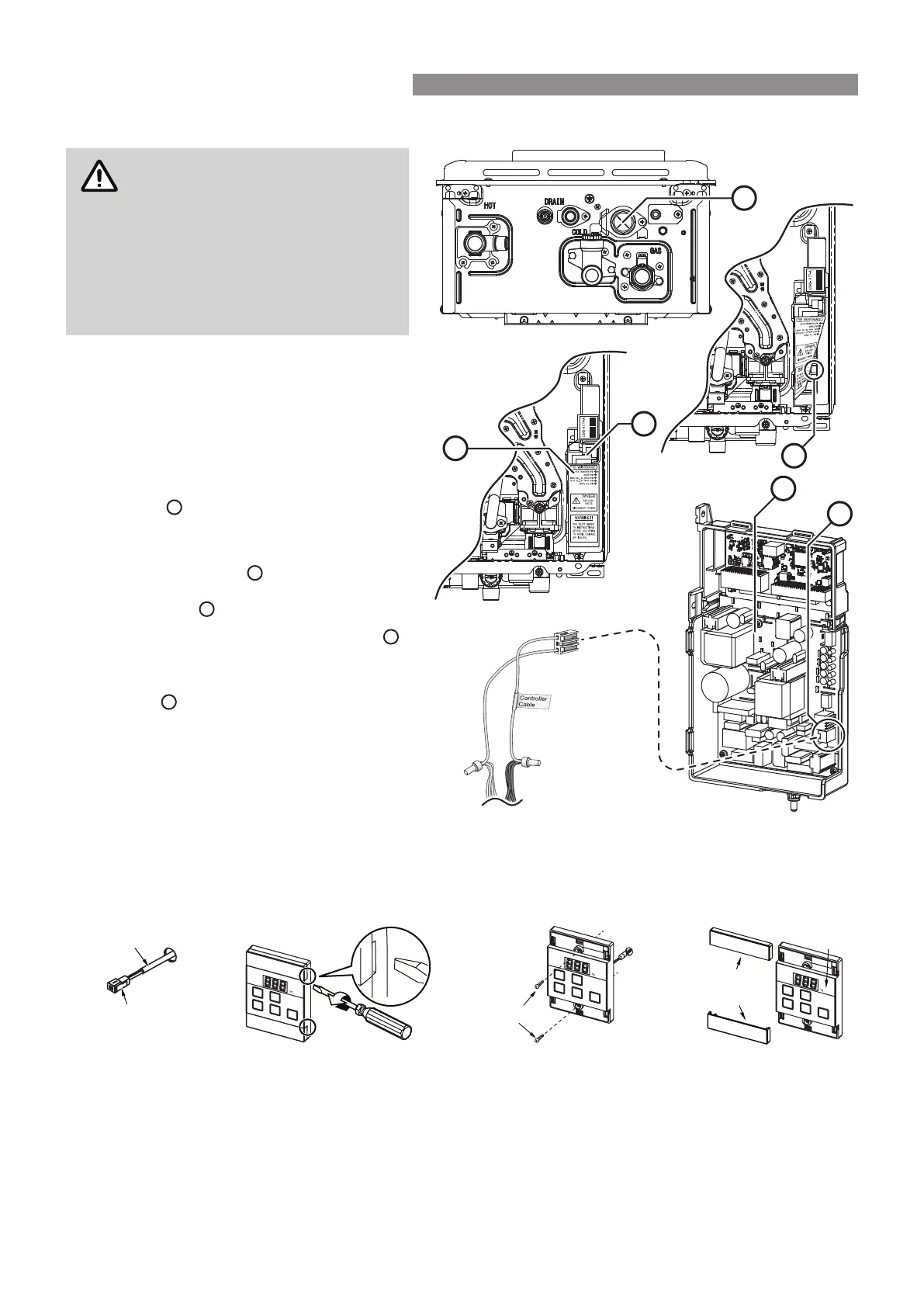
Connecting Communication Cables to PCB (REU-E)
Installation MUST be completed
by a qualied and licensed trades
person.
DO NOT attempt to connect mini-
plug or water controller cables
to the water heater unless the
electric power to the water heater is
switched ‘o’ otherwise damage to
electrical components may occur.
1. Isolate the electric power supply by
switching the power point o and removing
the power plug of the water heater from
the electric power socket.
2. Remove the front cover of the appliance.
3. Insert the mini-plug and the connected
water controller cables through the cable
access
at the base of the appliance.
Ensuring that the cable connectors are
located inside the appliance for protection.
4. Locate the PCB
B
, (bottom right of
appliance), and carefully rotate the plastic
safety cover
out of the way.
5. Locate the accessory port socket
D
(bottom front of the PCB).
6. Plug the mini-plug into the accessory port
socket
D
(the plug and socket are keyed
so that they can only be plugged in the one
direction).
7. Proceed with the water controller
installation and connect the communication
cables to controllers.
UNIVERSAL WATER CONTROLLER (MC-601Q) INSTALLATION
1. Determine the most suitable position, refer "Location" on page 26.
2. Mark and drill 3 holes (mounting and cable access) refer to "Table 1. Appliance Dimensions" on page 32
and "Diagram 1. Dimensions" on page 33 for water controller dimensions.
3. When running cable through the access hole ensure the connector end of the cable is located nearest to the
water controller (Fig. 1).
4. Carefully remove the cover plates from the water controller, using a screw driver (Fig. 2).
5. Connect the cable to the water controller. Feed any excess cable lengths into the wall cavity to avoid the
pinching of cables between the wall and the water controller.
6. Fix the water controller to the wall using the appropriate xings (Fig. 3).
7. Remove protective lm from the water controller face and replace the cover plates (Fig. 4).
D
B
A
C
B
D
Connector
Controller Cable
Screws
Film
Fig. 1 Fig. 2 Fig. 3 Fig. 4
Cover
Plates
WATER CONTROLLER INSTALLATION