41
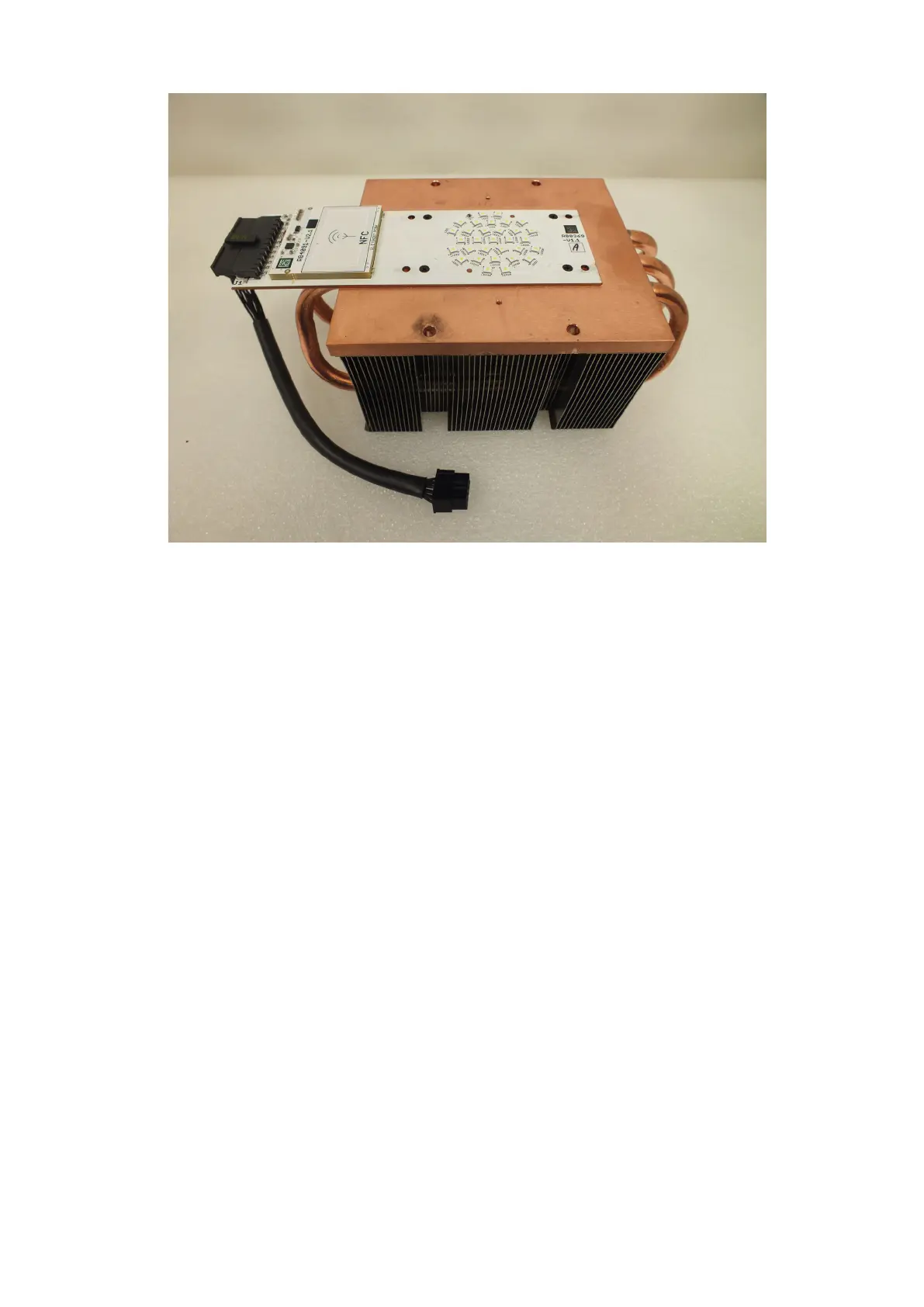
The LED module consists of the LED PCB (A) with LED source cable and the heatsink (B).
6. Screw the new LED module to the head by means of the he four socket cap screws M4x14 (7) with washers
7. Connect the cable connector (6) to the control PCB. Fasten the cable (5) to the holder by means of the cable
binder (4).
8. Screw the rear cover (3) back to the head by means of the the four screws M3x8 (2) with star washers.
9 Fasten the head covers back on the head and check their attachment including securing wires.
A
B