9-2
DIAPHRAGM
CARBURETOR
9-2-1
OPERATION
AND
CONSTRUCTION
1)
PUMP
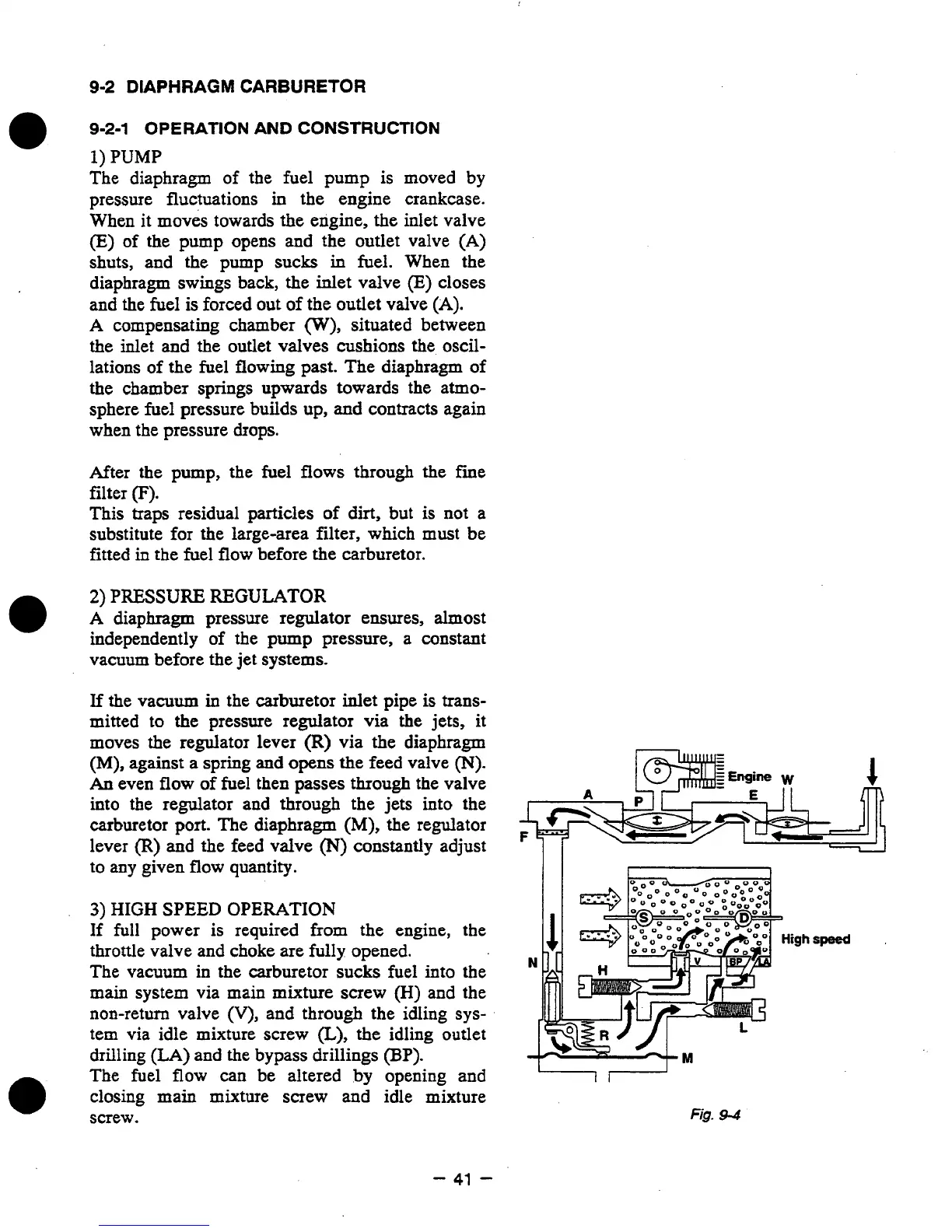
The diaphragm of the fuel pump is moved by
pressure fluctuations
in
the engine crankcase.
When it moves towards the engine, the inlet valve
(E)
of the pump opens and the outlet valve
(A)
shuts, and the pump sucks
in
fuel. When the
diaphragm swings back, the
inlet
valve
(E)
closes
and the fuel is forced
out
of
the outlet valve
(A).
A
compensating chamber
(W),
situated between
the inlet and the outlet valves cushions the
oscil-
lations of the fuel flowing past. The diaphragm of
the chamber
springs
upwards towards the atmo-
sphere fuel pressure builds up,
and
contracts again
when the pressure drops.
After the pump, the fuel flows through the fine
filter
(F).
This
traps
residual particles
of
dirt,
but
is
not a
substitute for the large-area filter, which must be
fitted
in the
fuel flow before the carburetor.
2)
PRESSURE
REGULATOR
A
diaphragm pressure regulator ensures, almost
independently of the pump pressure, a constant
vacuum before the jet systems.
If
the vacuum in the carburetor inlet pipe
is
trans-
mitted
to
the pressure regulator via the jets, it
moves the regulator lever
(R)
via the diaphragm
(M),
against a spring and
opens
the feed valve
(N).
An
even
flow
of fuel then
passes
through the valve
into the regulator and through the jets into the
carburetor port. The diaphragm
(M),
the regulator
lever
(R)
and the feed valve
(N)
constantly adjust
to
any
given
flow
quantity.
3)
HIGH
SPEED
OPERATION
If
full power is required
from
the engine, the
throttle valve and choke are fully opened.
The vacuum in the carburetor sucks fuel into
the
main system via main mixture screw
(H)
and the
non-return valve
(V),
and through the idling
sys-
tem via idle mixture screw
(L),
the idling outlet
drilling
(LA)
and the bypass drillings
(BP).
The fuel
flow
can be altered by opening and
closing main mixture screw and idle mixture
screw.
I1
3
High
speed
L”7+
Fig.
9-4
-
41
-