Do you have a question about the Robin FL-H7500 and is the answer not in the manual?
Detailed specifications for the engine blower, including dimensions, weight, engine type, and performance metrics.
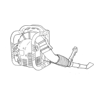
Step-by-step instructions for disassembling the main equipment components of the blower.
Lists specific tightening torques for various engine parts during reassembly.
Instructions for removing the pulley from the engine assembly.
Detailed procedure for removing the push rod, cover, cam lifter, and cam gear.
Instructions for removing the cylinder head assembly from the engine.
Procedure for removing the rocker arm, valve, and spring components.
Instructions for removing the flywheel and ignition coil assembly.
Procedure for removing the cylinder, crankshaft, and crankcase components.
Steps for removing the crankshaft, piston, piston rings, and oil ring.
Table detailing the specified tightening torques for various engine parts during reassembly.
Illustrates the process of disassembling and reassembling the carburetor components.
Outlines the step-by-step procedure for disassembling and reassembling the carburetor.
Details the checks required after carburetor reassembly to ensure proper function.
Step-by-step instructions for disassembling the recoil starter mechanism.
Detailed procedure for reassembling the recoil starter components correctly.
Troubleshooting guide for issues when the engine crankshaft fails to rotate.
Troubleshooting steps for engine starting issues related to fuel supply problems.
Diagnostic steps for low or insufficient compression in the engine cylinders.
Troubleshooting steps for issues related to the spark plug and ignition system.
Steps to check for and address abrasion or damage in engine parts like cylinders and pistons.
Specifies the bore diameter gauge, adjustment limit, and usage limit for cylinder reconditioning.
Specifies the acceptable height measurement for the cam top.
Guide on how to check and refill engine oil, including inspection and adding oil procedures.
Step-by-step instructions for draining old engine oil and refilling with new oil.
Detailed steps for adjusting the valve clearance at the compression top dead center using specific tools.
Daily cleaning and inspection schedule for the air cleaner element and associated parts.