CAN Networking on Roboteq Controllers
8 CANBus Networking Manual V2.0 July 8, 2019
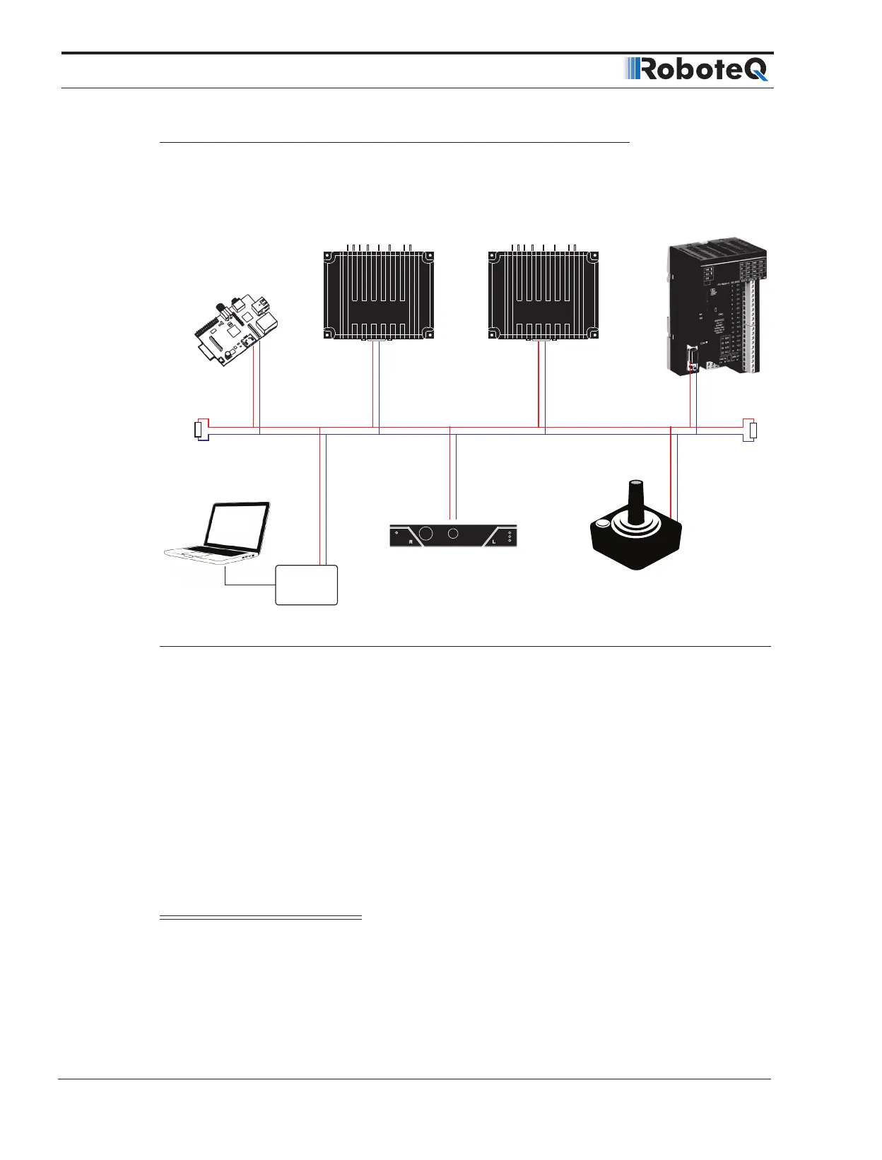
Connecting to CAN bus
A CAN bus network is made of a stretch of two wires. A device can be put on a CANbus
network by simply connecting it’s CAN-High and CAN-Low lines to those of other devices
on the network.
CANH
CANL
120Ω
Microcomputer
Joysticks, Batteries
HMI’s and other CAN Accessories
Magnetic Guide Sensor
Motor Controllers
PLC
CAN
Adapter
120Ω
Figure 1-1: CAN Network topology
Resistors should be 120 ohm and located at each end of the cable. However, on a short
network communication will take place with a single resistor of 100 to 200 ohm located
anywhere on the network. Communication will not work if no resistor is present, or if its
value is too high.
No ground connection is necessary in between nodes. However, the ground potential of
each node must be within a few volts of each other. If all devices on the network are pow-
ered from the same power source, this can be expected to be the case.
CANbus will be operational upon enabling the desired CAN protocol and speed using the
PC utility.
Important Warning
A ground difference up to around 10V is acceptable. A difference of 30V or higher
can cause damage to one or more nodes. CANbus isolators must be used if a similar
ground level cannot be guaranteed between nodes.
 Loading...