CANBus Networking Manual 49
SDO Description
Velocity Mode
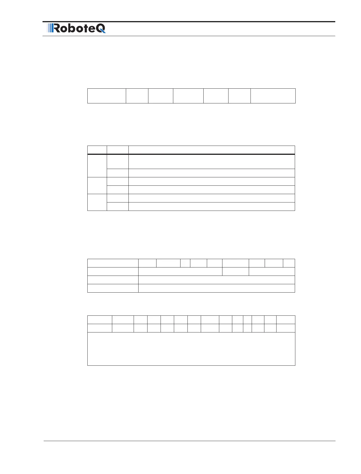
TABLE 4-10. control word mapping in Velocity Mode
15 9 8 7 6 5 4 3 0
see Table 4 Halt
see
Table 4
Reference
Ramp
Unlock
Ramp
Enable
Ramp
see Table 4
MSB LSB
In Velocity Mode the operation specific bits are mapped on Table 4-10. With bits 4, 5 and
6, user can configure the available ramp related options as shown in Table 4-11.
TABLE 4-11. Definition of bits 4,5 and 6 in Velocity Mode
Bit Value Definition
4
0
Motor shall be halted. Slow down on quick stop ramp (EDEC) and
stay in operation enabled
1 Velocity demand value shall accord with ramp output value
5
0 Ramp output value shall be locked to current output value
1 Ramp output value shall follow ramp input value
6
0 Ramp input value shall be set to zero
1 Ramp input value shall accord with ramp reference
0x6041 - Status Word
Table 4-12 gives a short description of the object, Table 4-13 the mapping of the respective
variable and Table 4-14 the usage of the bits that are independent to operation mode.
TABLE 4-12. Status Word
Sub-Index 00 Optional N Type U16 Access RO PDO T
Value Range Discrete Default -
RoboCommand SW
Description The status of the PDS FSA.
TABLE 4-13. Status Word Mapping
15 14 13 12 11 10 9 8 7 6 5 4 3 2 1 0
NU OMS ILA TR RM MS W SOD QS VE F OE SO RTSO
MSB LSB
NU Not Used, OMS Operation mode specific, ILA Internal limit active
TR Target reached, RM Remote, W Warning, SOD Switch on disabled,
QS Quick stop, VE Voltage enabled, F Fault, OE Operation Enabled,
SO Switch on RTSO Ready to switch on.
If bit 4 (voltage enabled) of the status word is always 1. If bit 5 (quick stop) of the status
word is 0, this shall indicate that the PDS is reacting on a quick stop request (quick stop
mode is always 2). Bit 7 (warning) is always 0. Bit 9 (remote) of the status word is al-
ways 1. If bit 10 (target reached) of the status word is 1, this shall indicate that the PDS
has reached the set-point. Bit 10 shall also be set to 1, if the operation mode has been
changed. The change of a target value by software shall alter this bit. If halt occurred
and the PDS has halted then bit 10 shall be set to 1, too. If the same internal value is
 Loading...