11
7. Repeat Steps 4-6 for the Left Metal Pivoting Leg (2) and
Left Side Rail (D).
8. Locate the center on each end of the solid-wood Leg Support
Rail (O) by drawing diagonal lines from corner to corner.
Drill a 1/4" diameter hole 1
1
⁄2" deep centered on the “X” at
each end. Don’t attach the rail to the Metal Pivoting Legs (1
and 2) at this time; wait until the piece has been finished.
9. Remove the Right and Left Metal Pivoting Legs (1 and 2)
to allow easy finishing of the Side Rails (C and D).
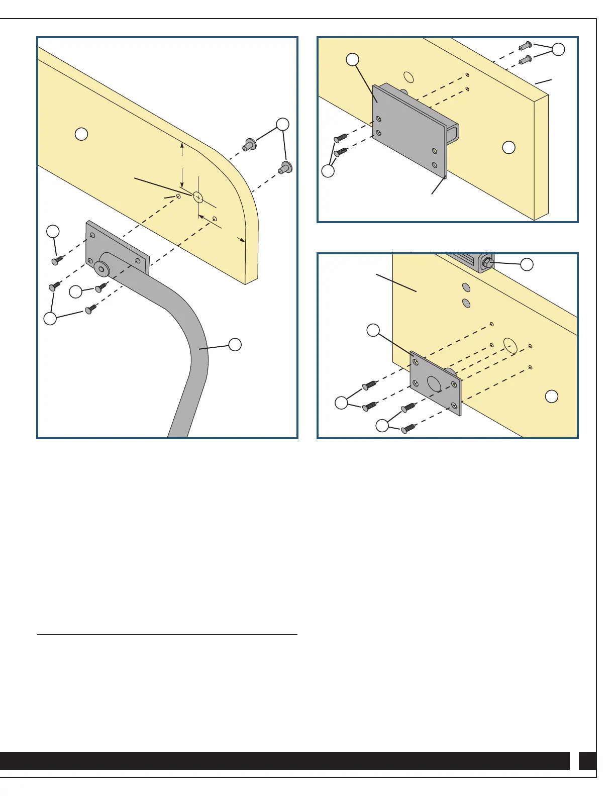
Install the Lower Ball Stud Plates
and Female Pivot Plates
1. Mark and drill 1" diameter through holes for the Female
Pivot Plates (10) toward the back of the Right and Left Side
Rails (C and D) at the location specified on the Shop
Drawing. Use a backer board to avoid tear-out.
2. Position the Right Lower Ball Stud Plate (7) on the Right
Side Rail (C) so that the channel rests on top of the rail,
with the plate on the outside and the hex adjustment head
facing the front end of the rail. Align the back edge of the
Right Adjustable Lower Plate with the back end of the Side
Rail and mark the front two hole locations. Fig. 3.
3. Drill 1/4" diameter through holes at the two marked
locations. Insert two T-Nuts (4) into the holes from the
inside face of the Right Side Rail (C). Attach the Right
Lower Ball Stud Plate (7) to the Right Side Rail with two
Machine Screws (5) threaded through the Plate into the
T-Nuts. Fig. 3.
4. Repeat Steps 3 and 4 to mount the Left Lower Ball Stud
Plate (8) on the Left Side Rail (D).
5. On the inside of each Side Rail (C and D), position a
Female Pivot Plate (10) with the pivot in the 1" through
hole. Use a square to align the plate; then mark screw
locations. Drill stopped pilot holes and attach each Female
Pivot Plate with four #12 x 3/4" Silver Screws (14). Fig. 4.
Fig. 2 Fig. 4
Fig. 3
C
2
1
⁄2"
5/8" diameter x
1/2" deep
1/4" diameter
3
1
⁄8"
5
3
1
3
4
Flush with back edge
of Right Side Rail (C)
C
Inside
face
8
C
Inside face
10
14
14
8
4
5