14
Install the Upper Ball Stud Plates
on the Bed Cabinet Verticals
1. On the inside face of each Bed Cabinet Vertical (I),
make a vertical mark 10" in from the front edge. Make
additional horizontal marks 29
1
⁄8" and 32
5
⁄8" up from
the bottom edge. Fig. 8.
2. Install a 3/4" straight bit in a plunge router that’s equipped
with an edge guide, or use a straightedge clamped to the
Bed Cabinet Vertical (I). Set the bit cutting depth to 1/4",
and set the edge guide or the straightedge so that the center
of the bit will be 10" from the front edge of the Bed Cabinet
Vertical. In other words, the bit should be centered on the
vertical mark you made in Step 1.
3. In each Bed Cabinet Vertical (I), carefully rout a
3/4" wide x 1/4" deep mortise between the horizontal
lines you marked in Step 1. Make sure to keep the router
tight against the guide and start and stop the mortise at
the inside edges of the lines while routing the mortise.
4. Insert an Upper Ball Stud Plate (15) in each mortise and
use the two mounting holes in the Upper Plate to mark
drilling locations. Remove the Upper Ball Stud Plate and
drill 1/4" diameter through holes at the marked locations,
using a backer board under the Bed Cabinet Verticals (I)
to prevent tear-out.
5. Place an Upper Ball Stud Plate (15) back in each mortise.
Insert a T-Nut (4) in each hole on the outside face of the
Bed Cabinet Verticals (I) and thread Machine Screws (5)
through the mounting holes in the Upper Ball Stud Plates
and into the T-Nuts. Tighten securely.
Install the Male Pivot Plates
on the Bed Cabinet Verticals
1. Make a mark 4
3
⁄4" in from the front edge and 11
3
⁄4" up
from the bottom edge on the inside face of each Bed
Cabinet Vertical (I). Fig. 8.
2. Drill a 5/8" diameter hole 1/2" deep centered at each
of these marks.
3. To mount each Male Pivot Plate (11), insert the
short (back) end of the pivot rod into the hole and use
a square to align the plate. Mark the locations of the upper
two screw holes and remove the Male Pivot Plate.
4. Drill 1/4" through holes at these locations, using a backer
board to avoid tear-out. Fig. 8.
5. From the outside face, insert two T-nuts (4) in the two holes.
6. Realign each Male Pivot Plate (11) with the holes and secure
with Machine Screws (5) threaded into the T-nuts (4). Drill
pilot holes and drive #12 x 3/4" Silver Screws (14) into the
plate’s remaining two holes.
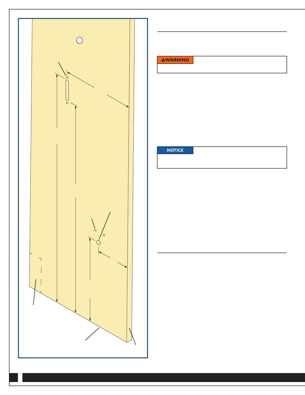
Fig. 8 - Bottom Edge of Bed Cabinet Verticals (I)
Turn off and unplug your router before
installing the bit or adjusting the cutter height.
The Ball Studs (16) and Ball Stud
Spacers (17) are not installed on the Upper Ball Stud
Plates (15) at this point.
Cut notches
to accommodate
base molding
if necessary
10"
32
5
⁄8"
29
1
⁄8"
4
3
⁄4"
11
3
⁄4"
I
5/8" diameter
1/2" deep
1/4" diameter
Bottom edge of Bed
Cabinet Verticals (I)
Front
edge
1/4" through hole