16
Install Mattress Support Panels
and Retaining Straps
1. With the help of another adult, if necessary, turn the bed
frame assembly over or position it upright and install the
desired cabinet pulls on the outside of the Bed Face
Panel (G). For optimal leverage, cabinet pulls should be
located between 5' and 6' from the bottom of the Bed
Face Panel.
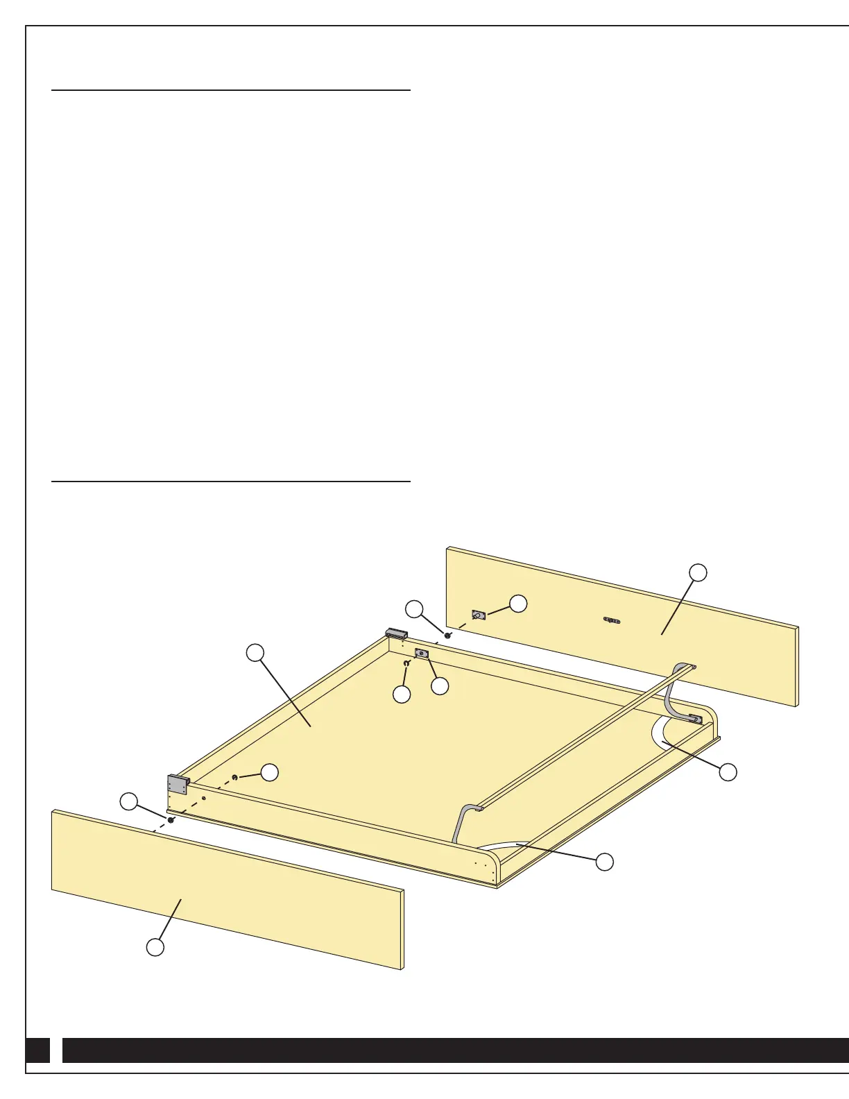
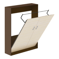
2. Reposition the bed frame assembly so the Bed Face
Panel (G) is facedown on a blanket or other nonmarring
surface. Position the Mattress Support Panel (N) on top of
the slats of the inner bed frame. Fig. 11.
3. Drill pilot holes and attach with eight #8 x 1
1
⁄4"
Coarse-Thread Screws. Do not use glue.
4. From each of the front corners, measure out 16" in both
directions and make marks near the edges of the Mattress
Support Panel (N), directly over the inner frame.
5. At each mark, attach one end of a Mattress Retaining
Strap (20) with a #8 x 1
1
⁄4" Coarse Thread Screw.
6. Reinstall the Metal Pivoting Legs (1 and 2) and Leg
Support Rail (O).
Attach the Bed Cabinet Verticals
and the Bed Headboard
1. Position the Bed Cabinet Verticals (I) on their front
edges, next to the corresponding side of the bed frame
assembly. Fig. 11.
2. Slide a Plastic Pivot Plate Spacer (12) on the bar of the
Male Pivot Plate (11) on each Bed Cabinet Vertical (I).
3. Position the Bed Cabinet Verticals (I) so that the pivot
bars go in the pivot holes in the assembled bed frame.
The ends of the pivot bars should protrude through
the pivot holes on the inside of the bed frame.
4. Snap the provided “E” Clips (13) in the grooves of the
pivot bars.
5. From the back bottom edge of each Cabinet Vertical (I),
measure up 15" and make a mark. Do the same at 18"
and 28". Fig. 12.
6. Position the Bed Headboard (H) between the Cabinet
Verticals (I) with its bottom edge at the 15" marks and
hold or clamp in place. Fig. 12.
7. Drill pilot holes through each Cabinet Vertical (I) into the
Bed Headboard (H) at the 18" and 28" marks. Fig. 12.
8. Secure the Bed Headboard to the Cabinet Verticals with
#8 x 2" Coarse-Thread Screws.
I
20
I
12
13
10
11
13
12
20
Fig. 11
N