Rockwell Automation Publication 1769-IN088A-EN-P - February 2011 11
Chapter
1
Install a 1769 Module
Before You Begin
Compact I/O is suitable for use in an industrial environment when installed in
accordance with these instructions.
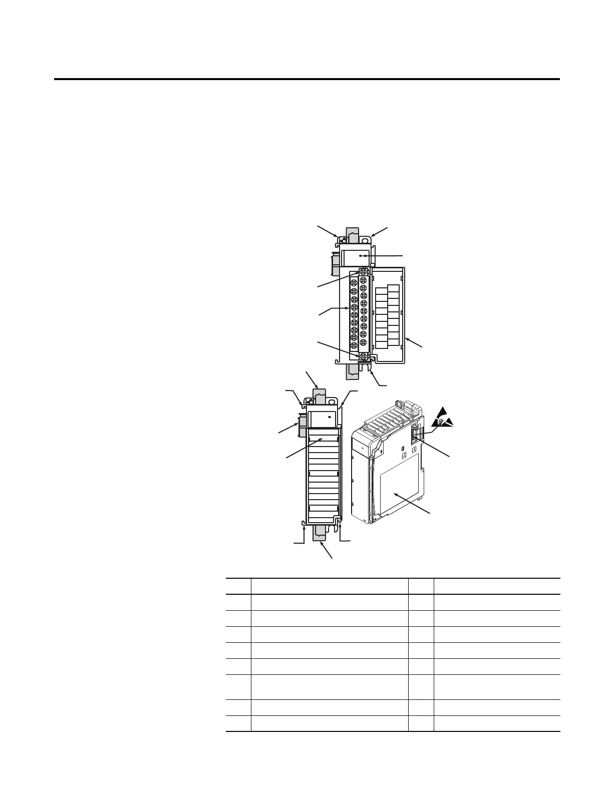
Item Description Item Description
1 Bus lever (with locking function) 7a Upper tongue-and-groove slots
2a Upper panel mounting tab 7b Lower tongue-and-groove slots
2b Lower panel mounting tab 8a Upper DIN rail latch
3 Module status LED 8b Lower DIN rail latch
4 Module door with terminal identification label 9 Write-on label (user ID tag)
5a Movable bus connector with female pins 10 Removable terminal block (RTB)
with finger-safe cover
5b Stationary bus connector with male pins 10a RTB upper retaining screw
6 Nameplate label 10b RTB lower retaining screw
10a
10b
4
10
2b
3
2a
1
5a
9
5b
6
7a
7b
8b
7b
8a
7a
1769-OF4VI
DANGER
Do Not Remove RTB Under Power
Unless Area is Non-Hazardous
Ensure Adjacent
Bus Lever is Unlatched/Latched
Before/After
Removing/Inserting Module
N/C
V out 1 +
N/C
V out 2 +
N/C
V out 3 +
N/C
V out 0 +
N/C
N/C
V out 1 -
N/C
V out 2 -
N/C
V out 3 -
N/C
V out 0 -
N/C
OK
Analog
OK
Analog

 Loading...


