Rockwell Automation Publication 1769-IN088A-EN-P - February 2011 87
I/O Memory Mapping Chapter 3
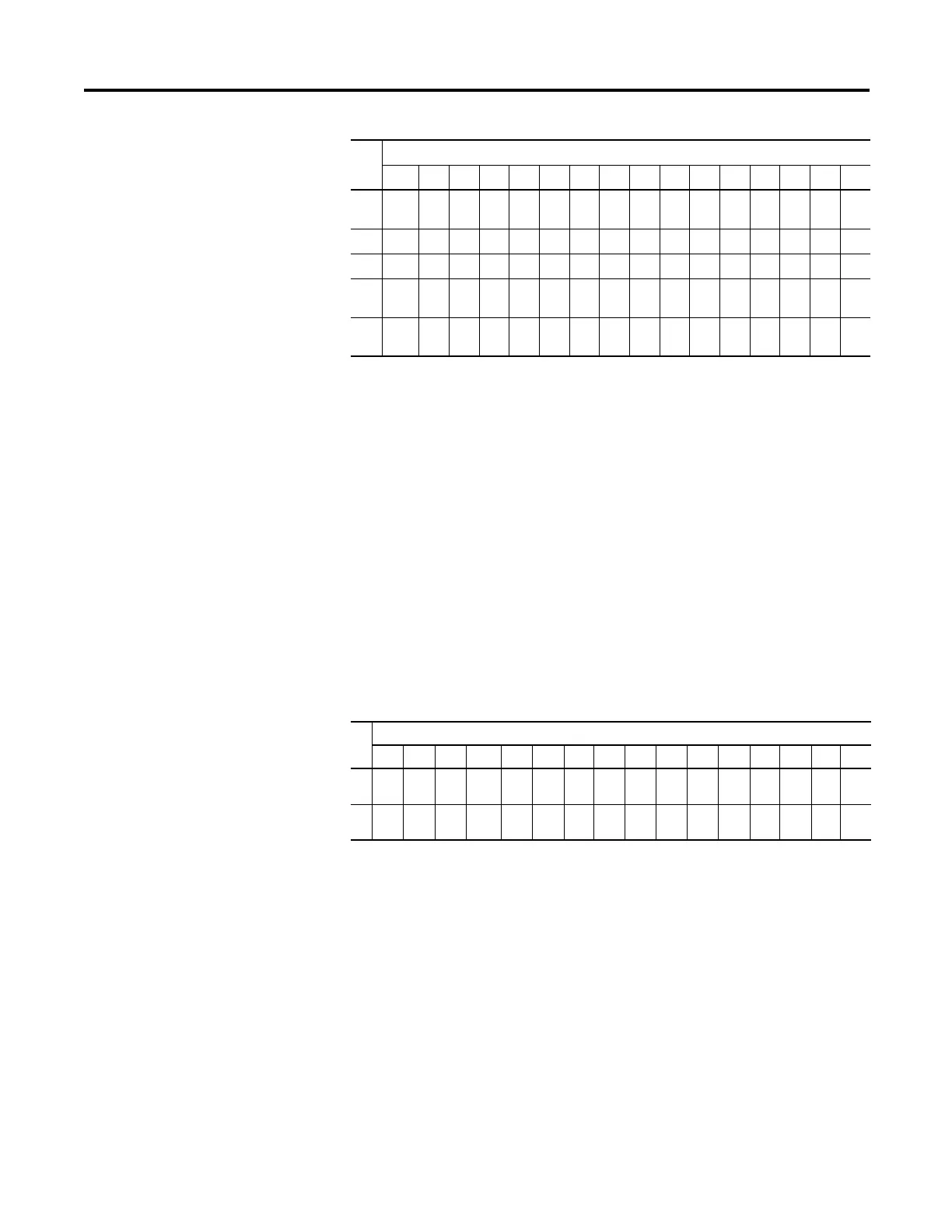
The bits are defined as follows:
• SGN = Sign bit in 2’s complement format.
• Nu = Not Used. Bit set to 0.
• Sx = General Status bit for input channels 0…15.
• Ox = Over range flag bits for input channels 0…15.
• Ux = Under range flag bits for input channels 0…15.
• Hx = High Alarm flag bits for input channels 0…15.
• Lx = Low Alarm flag bits for input channels 0…15.
Output Data File
For each module, slot x, words 0 and 1 in the output data file contain the cancel
latched channel alarm control bits.
The bits are defined as follows:
• CLHx = Cancel High Process Alarm Latch for Input x. Allows each input
high-process-alarm latch to be individually cancelled. Cancel = 1.
• CLLx = Cancel Low Process Alarm Latch for Input x. Allows each input
low-process-alarm latch to be individually cancelled. Cancel = 1.
17 S15 S
14
S
13
S
12
S
11
S
10
S9 S8 S7 S6 S5 S4 S3 S2 S1 S0
18 L3 H3 U3 O3 L2 H2 U2 O2 L1 H1 U1 O1 L0 H0 U0 O0
19 L7 H7 U7 O7 L6 H6 U6 O6 L5 H5 U5 O5 L4 H4 U4 O4
20 L11 H
11
U
11
O
11
L
10
H
10
U
10
O
10
L9 H9 U9 O9 L8 H8 U8 O8
21 L15 H
15
U
15
O
15
L
14
H
14
U
14
O
14
L
13
H
13
U
13
O
13
L
12
H
12
U
12
O
12
Word
Bit Position
15 14 13 12 11 10 09 08 07 06 05 04 03 02 01 00
0CLL
7
CLH
7
CLL
6
CLH
6
CLL
5
CLH
5
CLL
4
CLH
4
CLL
3
CLH
3
CLL
2
CLH
2
CLL
1
CLH
1
CLL
0
CLH
0
1CLL
15
CLH
15
CLL
14
CLH
14
CLL
13
CLH
13
CLL
12
CLH
12
CLL
11
CLH
11
CLL
10
CLH
10
CLL
9
CLH
9
CLL
8
CLH
8
Word
Bit Position
15 14 13 12 11 10 09 08 07 06 05 04 03 02 01 00

 Loading...


