30 Rockwell Automation Publication 440G-UM001B-EN-P - May 2016
Chapter 4 Description of Operation
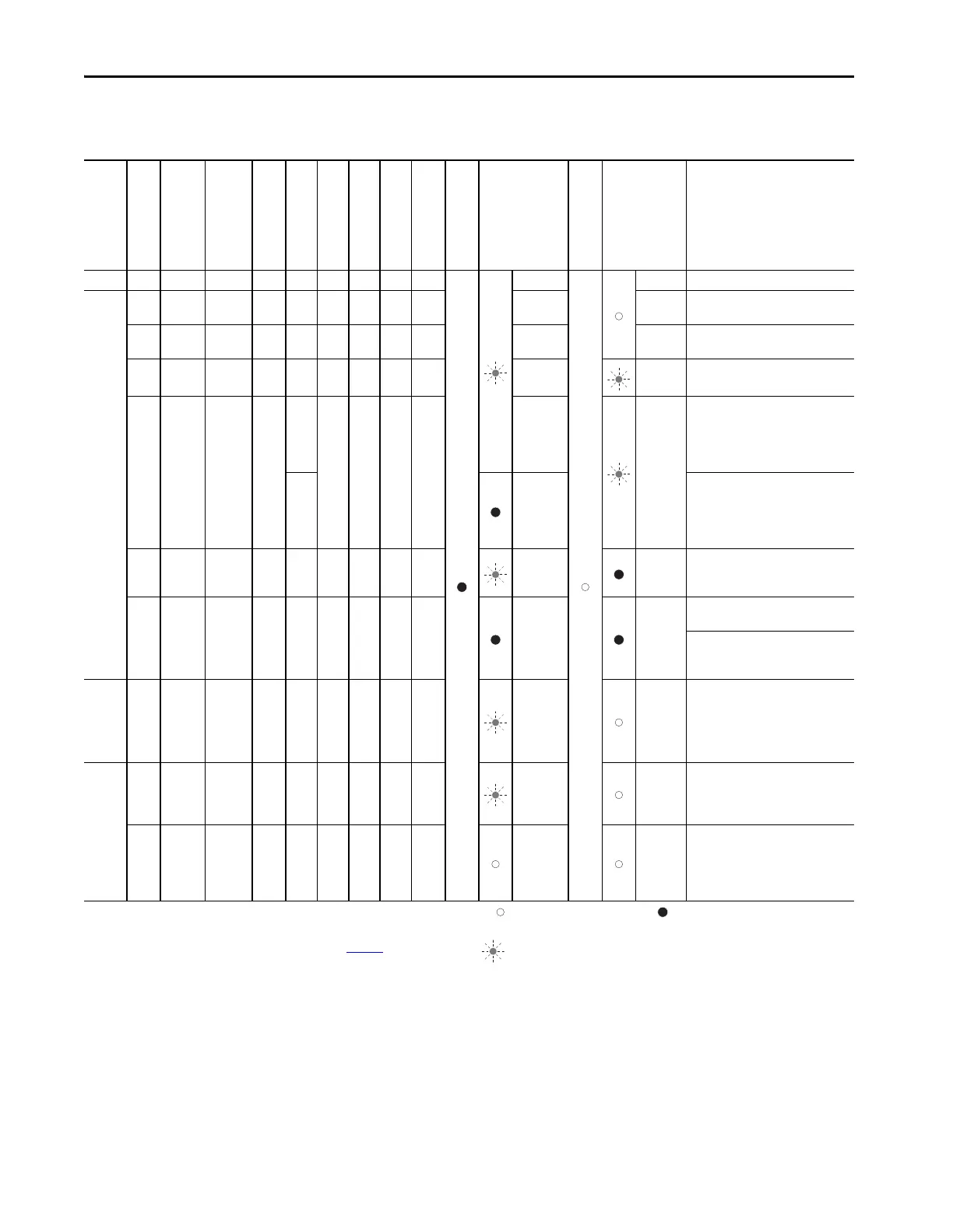
Status Diagnostic Status Indicators Table B (Series Operation)
Self-test X X X X OFF OFF OFF OFF OFF 5 Hz Self-test after power-up
XOpen
Not in-
serted
OFF OFF OFF OFF OFF OFF
Long OFF
Short ON
Normal operation, door is open
XClosed
Not in-
serted
OFF OFF OFF OFF OFF OFF
Long ON,
short OFF
Normal operation, door closed
OFF Closed In-serted OFF OFF ON ON OFF OFF
Long ON,
Short OFF
Long ON,
Short OFF
Normal operation, door closed, bolt
inserted safety inputs FI1A/FI1B OFF
ON Closed In-serted OFF
OFF
ON ON OFF OFF
Long ON,
short OFF
Long ON,
Short OFF
With active guard lock monitoring:
Normal operation, door closed, bolt
inserted. Safety inputs FI1A/FI1B are
ON. Safety outputs FO1A and FO1B
are OFF.
ON
With inactive guard lock monitoring:
Normal operation, door closed, bolt
inserted. Safety inputs FI1A/FI1B are
ON. Safety outputs FO1A and FO1B
are ON.
OFF Closed In-serted ON OFF ON ON ON OFF
Long ON,
Short OFF
Series Operation: Normal operation,
door closed and locked. Safety
outputs on the previous device OFF.
ONClosedIn-sertedONONONONONOFF
Operation as separate device: Normal
operation, door closed and locked.
Series Operation: Normal operation,
door closed and locked. Safety
outputs on the previous device ON.
XOpen
Not in-
serted
OFF OFF OFF OFF OFF OFF 3 x
Door is open: unit is ready for
configuration of another handle
assembly (only 3 minutes after
power-up).
X Closed In-serted ON OFF OFF OFF OFF OFF 2 Hz
Handle configuration tip: to prevent
interruption during configuration,
close door and switch on guard
locking.
X X X X OFF OFF OFF OFF OFF
Position acknowledgement after
completion of handle configuration.
Cycle power or apply 24V to RST for at
least 3 seconds to resume normal
operation.
* Latching fault; to reset, use the RST input or briefly disconnect the device from the
power supply.
** Non-latching fault; open safety guard and close it again to reset.
***See Troubleshooting and Assistance in Appendix A on page 59
.
Status indicator
not illuminated
status indicator illuminated
Status
indicato
r flashes
x
Any state
Position of the Bolt
Tongue
Safety Outputs
FO1A and FO1B
Door Mounting
Output (OD)
Monitoring Output
Bolt Tongue (OT)
Guard Locking Mon-
itoring Output (OL)
Diagnostics Moni-
toring Output (OI)
Handle Configuration
Set-up

 Loading...

