Rockwell Automation Publication 440G-UM001B-EN-P - May 2016 53
Chapter 6
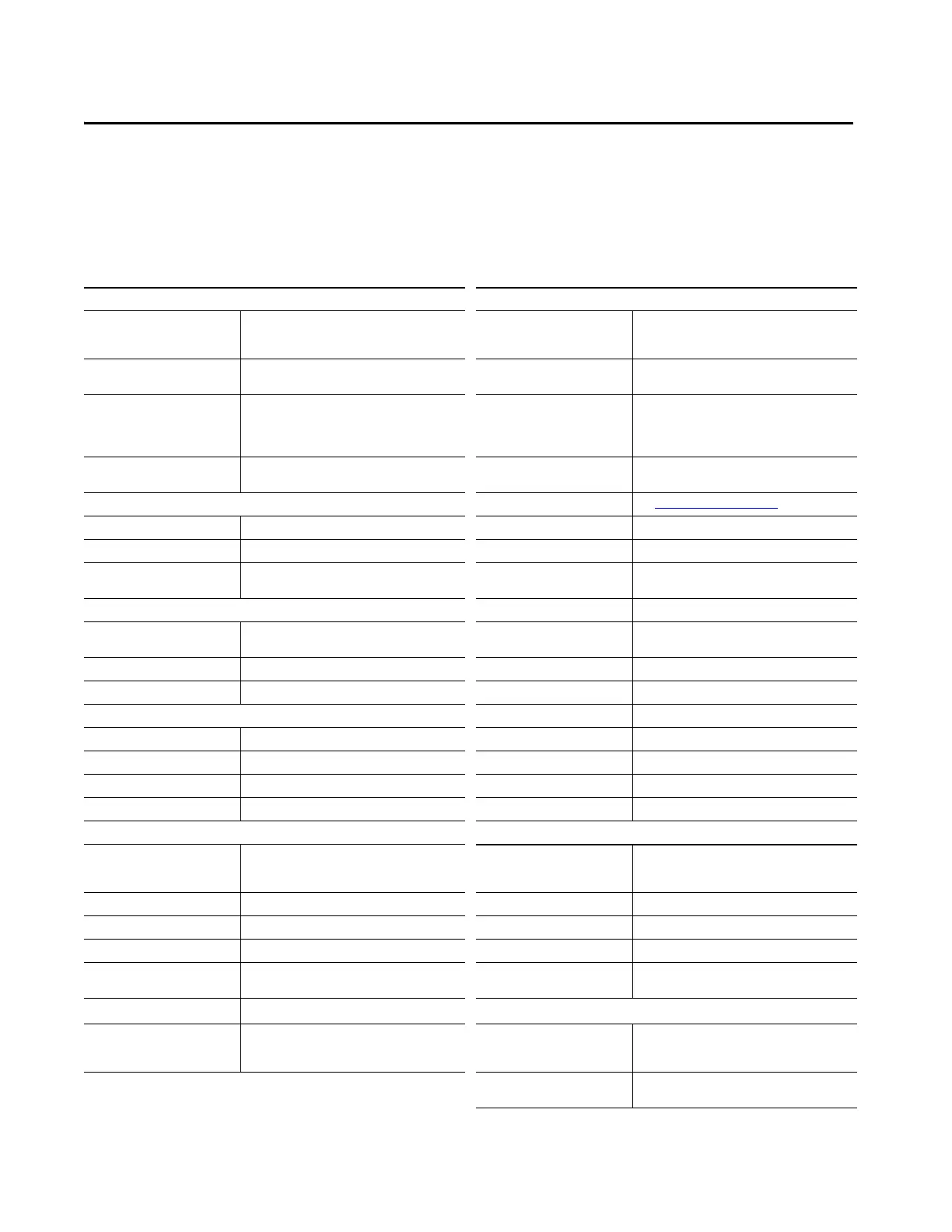
Specifications
Safety Ratings Operating Characteristics (continued)
Standards IEC 60947-5-3, EN ISO 13849-1, ISO 14119, UL 508
(evaluated for risks of electrical shock and fire; only
suitable for NFPA 79 applications only)
Protection Type Short circuit and reverse polarity protected, cross-fault
detection
Safety Classification Type 4 interlocking device with guard locking and high-
coded RFID actuators according to ISO 14119
Current Consumption I
UB
(no load on
any outputs)
80 mA
Functional Safety Data PFHd: 2.47 x 10
-8
; PLe, Cat. 4 (according to
ISO 13849-1).
Mission time: 20 years.
B10d for E-stop: 1.0 x 10
5
cycles
With energized guard locking
solenoid and unloaded outputs
OI,OL,OT, and OD
350 mA
Certifications cULus (UL 508) and CE Marked for all applicable
EUdirectives
Push button (no load, per status
indicator)
5 mA
Outputs External Fuse See Electrical Connection
on page 23
Safety Outputs (FO1A/FO1B) Semiconductor outputs, PNP Response Time (On) 570 ms
Output Current, maximum (each) 200 mA Response Time (Off) 350 ms first switch, 5 ms each additional switch
Output voltage U
FO1A
/ U
FO1B
1
@
50mA switching current
ON: U
B
- 2V…UB, OFF: 0…1V DC Risk Time (per IEC 60947-5-3) 350 ms
Monitoring Outputs Discrepancy Time 10 ms (maximum)
Monitoring Outputs (OD, OT, OL, OI) P-switching and short circuit-proof Start-up Time (availability) 0.5 s configured for standalone operation
8 s configured for series operation
Output Voltage U
A
- 2V…U
A
Maximum Length of Switch Chain 10 MAB devices
Maximum Load (each) 50 mA, maximum Utilization Category (IEC 60947-5-2) DC-13 24V 200 mA
Push Button Controls and Indicators Insulation Voltage U
i
(IEC 60947-1) 30V
Operating Voltage 5…24 V DC Impulse Withstand Voltage U
imp
1.5 kV
Operating Current 1…100 mA Pollution Degree (IEC 60947-1) 3
Breaking Capacity, maximum 250 mW Manual Release Built in (ISO 14119)
Power Supply status indicator 24V DC Mechanical Life 1,000,000 operations
Operating Characteristics Environmental
Torque Settings, maximum 1 Nm lock module cover screws (6x)
0.5 Nm manual release locking screw
2 Nm handle set screw (handle and escape release)
Ambient Temperature [C (F)]
at U
B
= DC 24V
-20…+55° (-4…+131°)
Locking Force Fmax 2600 N Storage Temperature [C (F)] -20…+65° (-4…+149°)
Holding Force Fzh (ISO 14119) 2000 N Enclosure Rating IP65
Maximum Impact Energy Withstand 300 J Operating Humidity 5…80% relative
Locking Bolt Alignment Tolerance Horizontal: ± 4 mm (0.16 in.); Vertical: ± 5 mm (0.2 in.) Vibration/Shock IEC 60068-2-27 30 g (1.06 oz), 11 ms/IEC 60068-2-6
10…55 Hz
Operating Voltage U
B
Class 2 PELV 24V DC +10/-15% required Physical Characteristics
Auxiliary Power U
A
Class 2 PELV 24V DC +10/-15% required Weight Lock module with cover 750 g (26.45 oz), handle
assembly 1000 g (35.27 oz), Escape release 500 g
(17.64oz))
Materials Glass fiber reinforced plastic, nickel-plated die-cast zinc,
anodized aluminum handle, stainless steel hardware

 Loading...

