8 Rockwell Automation Publication 440G-UM001B-EN-P - May 2016
Chapter 1 General Description
With INACTIVE Guard Lock Monitoring:
In combination with a movable separating safety guard and the control system,
this safety device prevents dangerous machine movements from occurring
while the safety guard is open. A stop command is triggered if the safety guard
is opened during the dangerous machine function. The position of the guard
locking is not considered during this process.
Safety outputs (FO1A, FO1B) are enabled only when the locking bolt is sensed
in its extended position in the lock module (i.e, the guard door is closed and
the bolt is extended). In this mode, the status of the guard locking is not
considered.
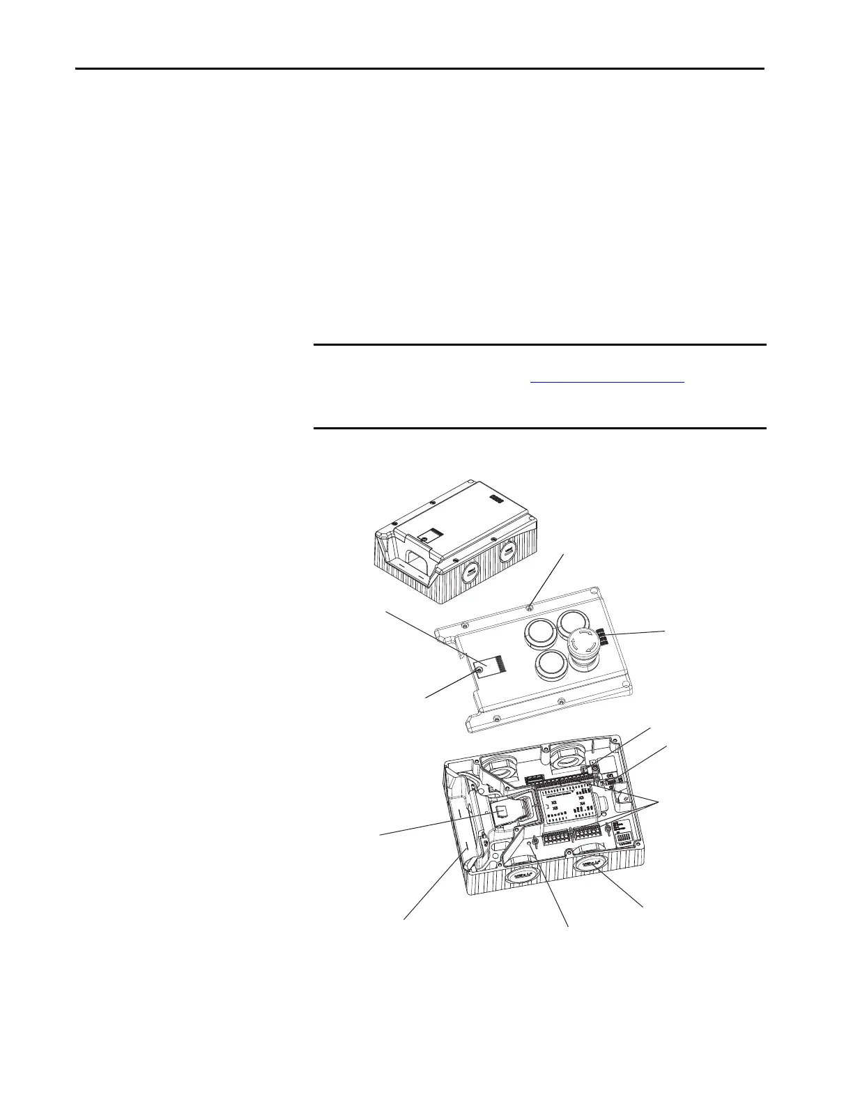
Assembly Overview
Figure 1 - Locking Module with Control Cover
* Apply to hardware revision B and higher.
IMPORTANT The safety outputs (FO1A, FO1B) are not enabled until a handle assembly
has been configured (see Handle Configuration
on page 15). After
configuration is completed, the lock module will only recognize the unique
code of the configured handle.
Manual Release
Cover
Terminals X2-X5
DIP Switches
Status/Diagnostic
Status Indicators
Locking Bar
Cable Entry M20 x 1.5 or
QD Connector (version-
dependent)
1 x Torx T8
6 x Torx T10
Marking for Maximum
Mounting Distance
Internal Reset*
Jumper*

 Loading...

