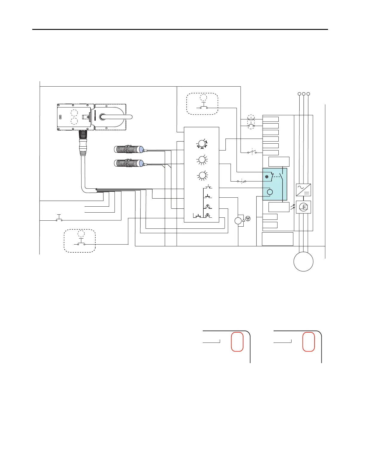
In this example The Unlock Request initiates a category 1 stop.
The MAB and GLP provide a speed monitored guard lock function.
The MAB and GLP provide a prevention of unexpected start-up function.
Hardware Rev. B
Note 1: U : Connected to 24V internally in MAB
OL: True when the door is closed, the bolt is extended and locked.
OT: True when the door is closed and the bolt is extended, locked
or not.
A
MAB cover
Reset/Lock
Blue
Brown
Yellow/
Brown
Green/
Black
Red/Blue
Unlock Cmd A
- see Note 1
Unlock Cmd B
Violet
Gray/Brown
White/Green
Pink
Blue
Black
Brown
Blue
Black
Brown
- see Note 3
White
Gray/Pink
Reset MAB
MAB cover
Unlock Request
AC Line
Input Power
Stop
- see Note 2
Rev. BRev. A
Note 2: Configured for three-wire control (external supply)
Dig in 4 is configured for speed sel 1, preset speed 1 (5.0 Hz)
Important: The drive enabled digital input is a solid-state circuit.
Pulse tested outputs should not be used with PF 70 digital inputs
Note 3: K1 2 = 700-HPS2Z24 with 700-HN123 terminal socket and
700-ADL1R surge suppressor with red status indicator.
Note 4: When using a Hardware Rev. A MAB, connect the violet wire to terminal 51
of the GLP. The gray/brown wire must remain unconnected.
Note that the terminal designations of X3.6 and X3.7 are different on
Hardware Rev. A and Hardware Rev. B MAB.
Gate Control
Power
Start
Digin
Enable
- see Note 1
Gate Control
Circuit
Common
* Jumpers
ENABLE Installed
SAFETY Removed

 Loading...

