60 Rockwell Automation Publication 442G-UM001B-EN-P - May 2016
Appendix A Troubleshooting and Assistance
Remedy:
1. Check the DIP switch setting. Configuration must be repeated if the
setting is incorrect. Follow the instructions in “Changing Device
Configuration” on page 34
.
Function of the switches
DIA LED Illuminated and State LED Flashes Two Times (standalone
operation only)
Fault: Input error.
Possible causes:
• 24V DC missing at safety inputs Fl1A and/or Fl1B
• A safe control system with clocking outputs is connected to safety inputs
FI1A and/or FI1B.
Remedy:
1. Check the wiring and correct it if necessary or switch to standalone mode.
2. Switch off the voltage or press the reset button (if present) that controls the
integrated reset input.
3. Close the door(s).
4. Switch the voltage on again or release the reset button.
5. Wait until the State LED flashes at regular intervals.
The Access Box is now ready for operation again.
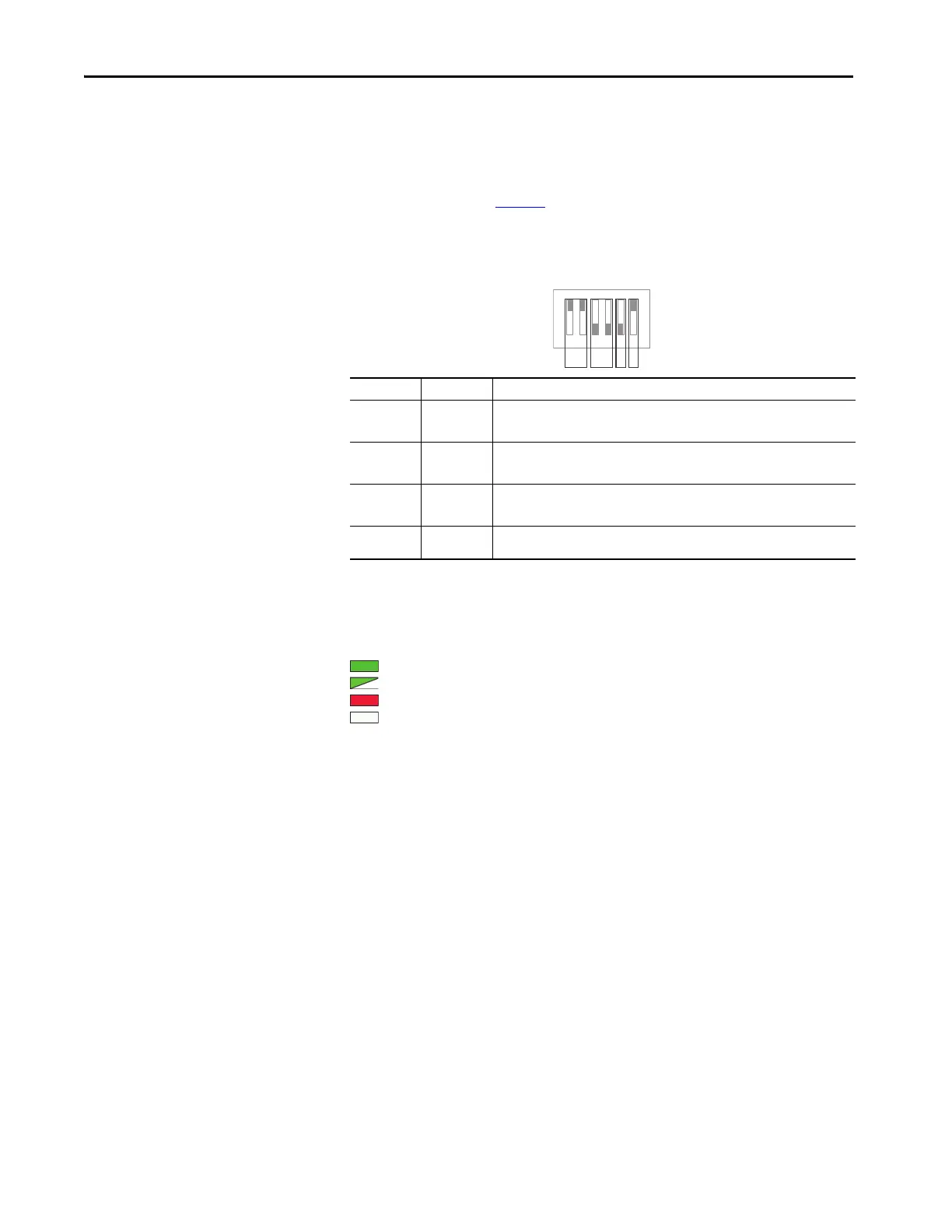
Detail Switch Function
1
A1+2
On: Device is configured for standalone operation (factory setting)
Off: Device is configured for series operation
B3+4
On: Guard lock monitoring is deactivated
Off: Guard lock monitoring is activated (factory setting)
C5
On: DIP switch configuration enabled
Off: DIP switch configuration inhibited (factory setting)
D6
On: Release monitoring is activated (factory setting)
Off: Release monitoring is deactivated
123456
A
BCD
ON
Factory settings are
shown.
Power
State 2 x flash
DIA
Lock

 Loading...

