8 Rockwell Automation Publication 2198-IN001D-EN-P - February 2016
Kinetix 5500 Servo Drives
Motor Brake (BC) Connector Pinout
Digital Inputs (IOD) Connector Pinout
Safe Torque Off (STO) Connector Pinout
The 2198-Hxxx-ERS drives ship with the safe torque-off function enabled. Connect the safe torque-off inputs to a safety circuit or install bypass
wiring to enable motion. Refer to the Kinetix 5500 Servo Drives User Manual, publication 2198-UM001, for more information.
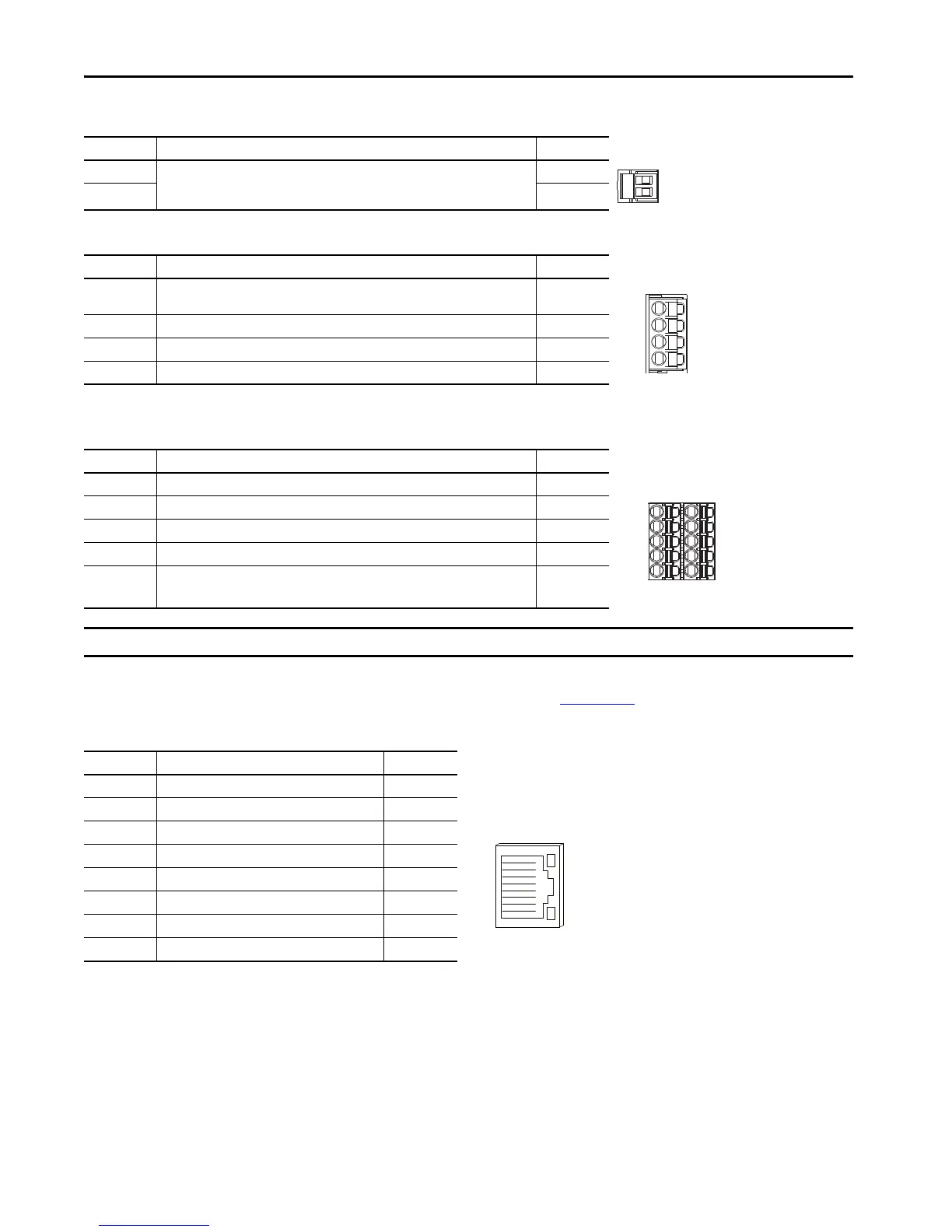
Ethernet Communication PORT1 and PORT2 Pinout
BC Pin Description Signal
1
Motor brake connections
MBRK+
2 MBRK-
IOD Pin Description Signal
1
24V current-sinking fast input #1.
This is a dual-function input.
IN1
(1)
(1) This signal has dual-functionality. You can use IN1 (IOD-1) as registration or Home input.
2 I/O common for customer-supplied 24V supply. COM
3 24V current-sinking fast input #2. IN2
4 I/O cable shield termination point. SHLD
STO Pin Description Signal
1 Safety bypass plus signal. Connect to both safety inputs to disable the STO function. SB+
2 Safety bypass minus signal. Connect to safety common to disable the STO function. SB-
3 STO input 1 (SS_IN_CH0). S1
4STO input common (SCOM). SC
5 STO input 2 (SS_IN_CH1). S2
IMPORTANT The safe torque-off (STO) connector applies to only the 2198-Hxxx-ERS drives.
Port Pin Description Signal
1 Transmit port (+) data terminal TD+
2 Transmit port (-) data terminal TD-
3 Receive port (+) data terminal RD+
4– –
5– –
6 Receive port (-) data terminal RD-
7– –
8– –
2
1

 Loading...


