Appendix B
HIM Overview
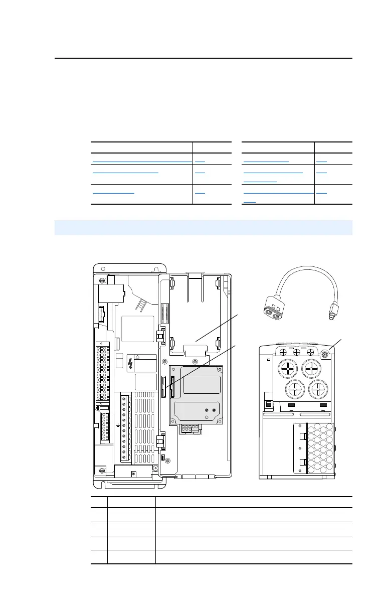
The PowerFlex 700 provides a number of cable connection points
(0 Frame shown).
For information on . . See page . . For information on . . See page . .
External and Internal Connections
B-1 Menu Structure B-3
LCD Display Elements B-2 Viewing and Editing
Parameters
B-5
ALT Functions B-2 Removing/Installing the
HIM
B-8
External and Internal Connections
No. Connector Description
➊
DPI Port 1 HIM connection when installed in cover.
➋
DPI Port 2 Cable connection for handheld and remote options.
➌
DPI Port 3 or 2 Splitter cable connected to DPI Port 2 provides additional port.
➍
DPI Port 5 Cable connection for communications adapter.
BR1
BR2
DC+
DC–
PE
U/T1
V/T2
W/T3
R/L1
S/L2
T/L3
Optional
Communications
Module
Use 75C Wire Only
#10-#14 AWG
Torque to 7 in-lbs
!
DANGER
20B-UM001.book Page 1 Thursday, June 20, 2013 1:55 PM

 Loading...


