2-2 Troubleshooting
The condition or state of your drive is constantly monitored. Any
changes will be indicated through the LEDs and/or the HIM (if present).
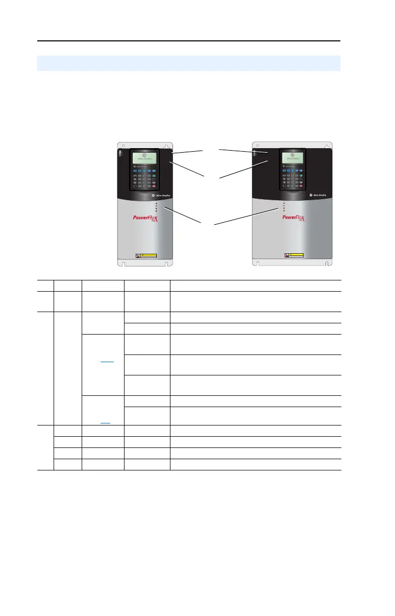
Front Panel LED Indications
Figure 2.1 Typical Drive Status Indicators
Drive Status
Esc
7 8 9
4 5 6
1 2 3
.
0 +/-
Sel
Jog
Alt
POWER
STS
PORT
MOD
NET A
NET B
Exp
Param #
S
.M
.
A
.
R
.
T
.
E
x
it
L
a
n
g
A
u
to
/ M
a
n
R
e
m
o
v
e
HOT surfaces can cause severe burns
CAUTION
Esc
7 8 9
4 5 6
1 2 3
.
0 +/-
Sel
Jog
Alt
POWER
STS
PORT
MOD
NET A
NET B
Exp
Param #
S
.M
.A
.R
.T
.
E
x
it
L
a
n
g
A
u
t
o
/ M
a
n
R
e
m
o
v
e
HOT surfaces can cause severe burns
CAUTION
# Name Color State Description
➊
PWR
(Power)
Green Steady Illuminates when power is applied to the drive.
➋
STS
(Status)
Green Flashing Drive ready, but not running & no faults are present.
Steady Drive running, no faults are present.
Ye l l ow
See
page 2-10
Flashing,
Drive Stopped
A start inhibit condition exists, the drive cannot be
started. Check parameter 214 [Start Inhibits].
Flashing,
Drive Running
An intermittent type 1 alarm condition is occurring.
Check parameter 211 [Drive Alarm 1].
Steady,
Drive Running
A continuous type 1 alarm condition exists.
Check parameter 211 [Drive Alarm 1].
Red
See
page 2-4
Flashing Fault has occurred. Check [Fault x Code] or Fault Queue.
Steady A non-resettable fault has occurred.
➌
PORT Green – Status of DPI port internal communications (if present).
MOD Yellow – Status of communications module (when installed).
NET A Red – Status of network (if connected).
NET B Red – Status of secondary network (if connected).
20B-UM001.book Page 2 Thursday, June 20, 2013 1:55 PM

 Loading...


