1-38 Programming and Parameters
Utility File
DYNAMIC CONTROL
Power Loss
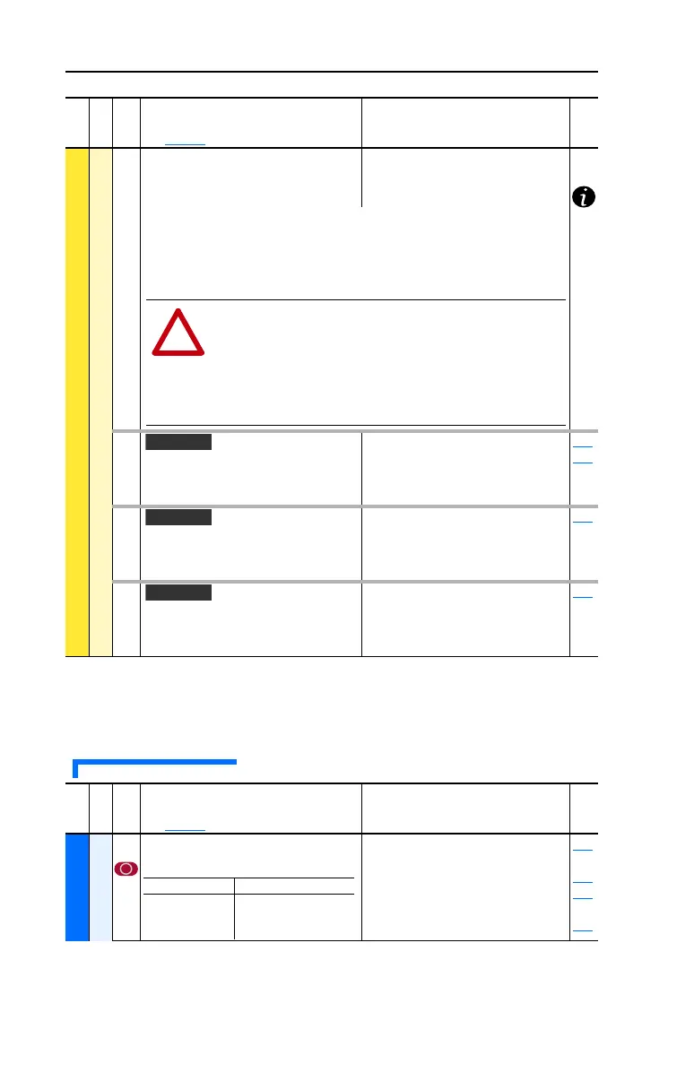
186 [Power Loss Level]
Sets the level at which the [Power Loss
Mode] selection will occur.
Default:
Min/Max:
Units:
Drive Rated Volts
0.0/999.9 VDC
0.1 VDC
187 [Load Loss Level]
Sets the percentage of motor nameplate
torque at which a load loss alarm will
occur.
Default:
Min/Max:
Units:
200.0%
0.0/800.0%
0.1%
211
259
188 [Load Loss Time]
Sets the time that current is below the
level set in [Load Loss Level] before a
fault occurs.
Default:
Min/Max:
Units:
0.0 Secs
0.0/30.0 Secs
0.1 Secs
187
189 [Shear Pin Time]
Sets the time that the drive is at or above
current limit before a fault occurs. Zero
disables this feature.
Default:
Min/Max:
Units:
0.0 Secs
0.0/30.0 Secs
0.1 Secs
238
File
Group
No.
Parameter Name & Description
See page 1-2 for symbol descriptions
Values
Related
The drive can use the percentages referenced in [Power Loss Mode] or a trigger
point can be set for line loss detection as follows:
V
trigger
= [DC Bus Memory] – [Power Loss Level]
A digital input (programmed to “29, Pwr Loss Lvl”) is used to toggle between
fixed percentages and the detection level.
ATTENTION: Drive damage can occur if proper input impedance
is not provided as explained below.
If the value for [Power Loss Level] is greater than 18% of [DC Bus
Memory], the user must provide a minimum line impedance to limit
inrush current when the power line recovers. The input impedance
should be equal to or greater than the equivalent of a 5%
transformer with a VA rating 5 times the drives input VA rating.
File
Group
No.
Parameter Name & Description
See page 1-2 for symbol descriptions
Values
Related
UTILITY
Direction Config
190 [Direction Mode]
Selects method for changing direction.
Default:
Options:
0
0
1
2
“Unipolar”
“Unipolar”
“Bipolar”
“Reverse Dis”
320
thru
327
361
thru
366
Mode Direction Change
Unipolar Drive Logic
Bipolar Sign of Reference
Reverse Dis Not Changeable
20B-UM001.book Page 38 Thursday, June 20, 2013 1:55 PM

 Loading...


