Publication 2098-IN005C-EN-P — March 2008
12 Commissioning Your Ultra3000 Drive
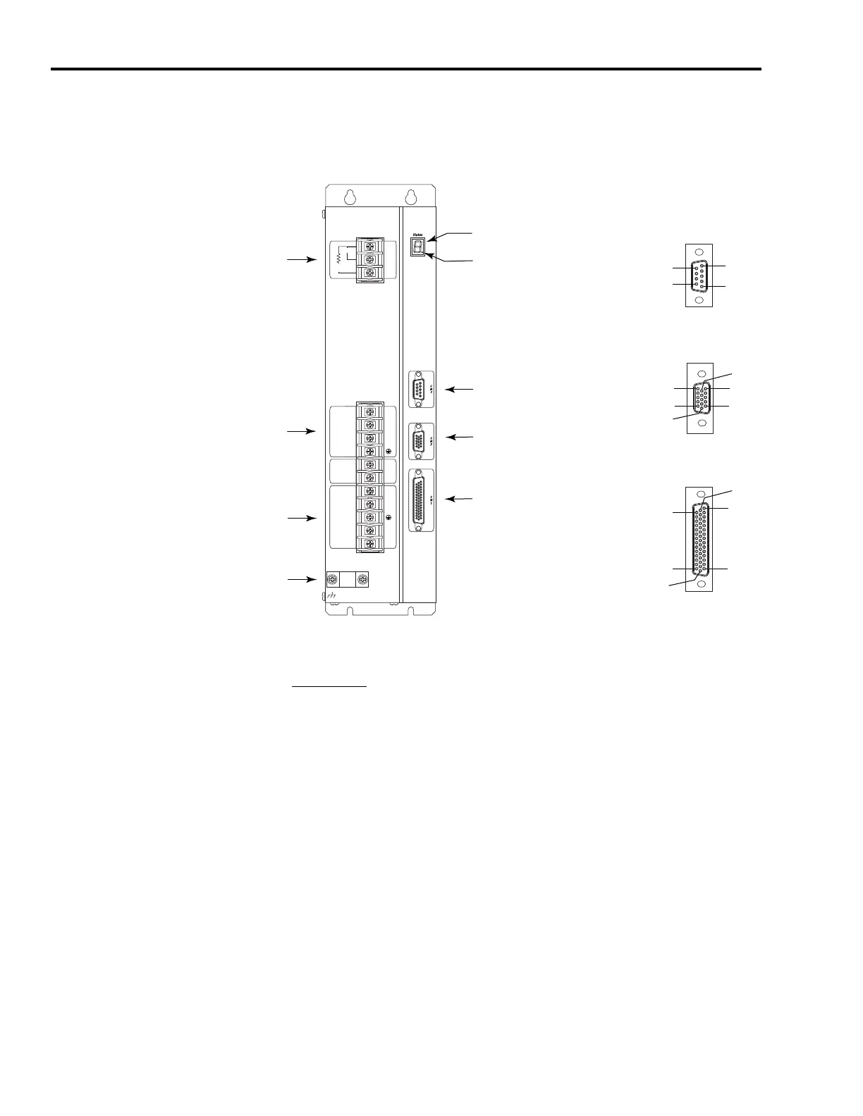
Use this figure to locate the front panel connections on the Ultra3000
230V drives (3 kW).
Front Panel Connections for 2098-DSD-030 and 2098-DSD-030X Drives
For CN1, CN2, and CN3 connector pin-out information, refer to the
Ultra3000 Digital Servo Drives Installation Manual, publication
2098-IN003
.
U
V
W
+
-
L1
L2/N
L1
AUX
L2/N
AUX
1
2
3
Motor
DC Bus
100-240 VAC
50/60 Hz
Internal
External
Shunt
TB1
TB2
Pin 11
Pin 6
Pin 15
Pin 1
Pin 10
Pin 5
Pin 30
Pin 44
Pin 1
Pin 15
Pin 16
Pin 31
Pin 6
Pin 9
Pin 1
Pin 5
AC Input Power
Connections
Motor Power
Connections
Passive Shunt
Resistor Connections
Seven-segment
Status Indicator
Logic Power Status Indicator
CN3 9-pin
Serial Port
Connector
CN2 15-pin
Motor Feedback
Connector
CN1 44-pin
User I/O
Connector
Motor Power
Cable Shield Clamp
9-pin CN3
Serial Connector
15-pin CN2
Feedback Connector
44-pin CN1
I/O Connector

 Loading...


