Publication 2098-IN005C-EN-P — March 2008
Interconnect Diagrams 127
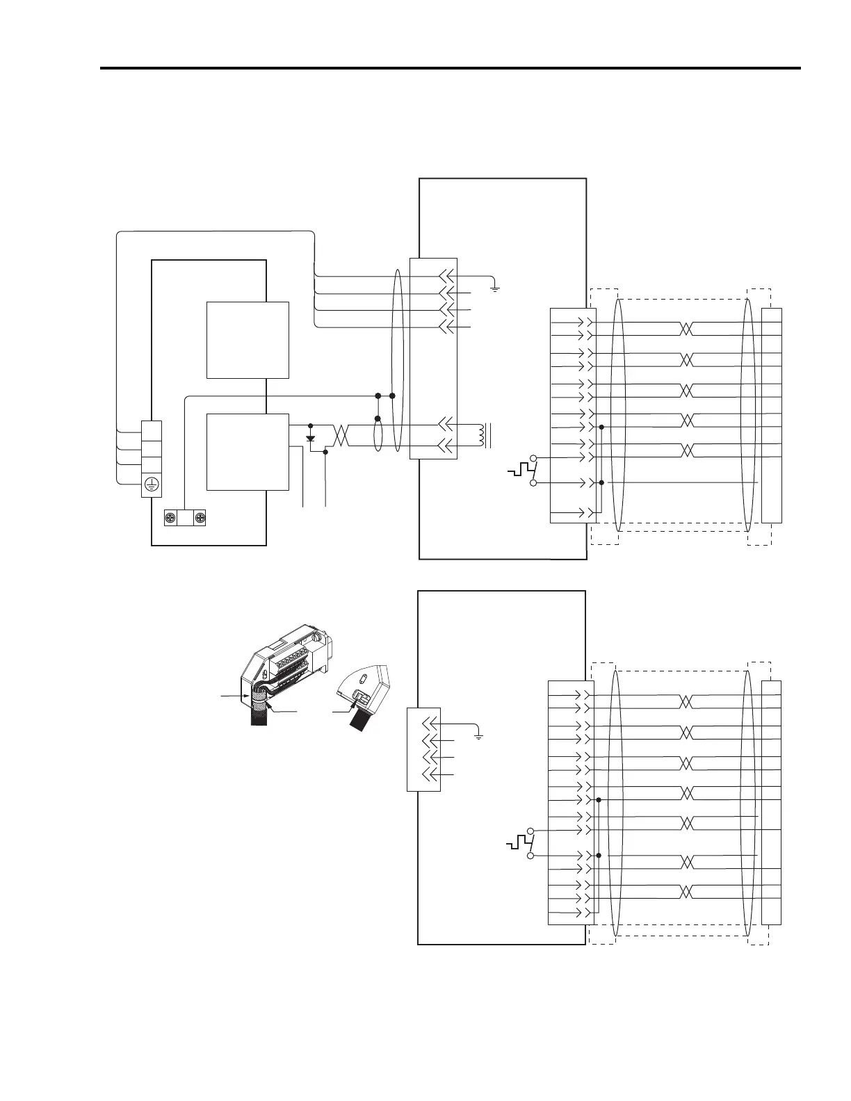
Ultra3000 Drives/Linear Actuators Wiring Examples
Wiring Example with MPAS-A/B (MP-Series) Linear Stages
BR+
BR-
W
V
U
GND
SIN+
SIN-
COS+
COS-
DATA+
DATA-
GREEN
WHT/GREEN
GRAY
WHT/GRAY
BLACK
WHT/BLACK
RED
WHT/RED
1
2
3
4
5
10
14
6
+9VDC
TS+
ORANGE
WHT/ORANGE
7
11
W
V
U
GND
+5VDC
ECOM
43
44
+24V
COM
U
V
W
3
4
5
6
1
2
9
10
14
12
11
13
D
C
B
A
F
G
D
C
B
A
BRN
BLK
BLU
GN/YL
TS-
COM
BLUE
AM+
AM-
BM+
BM-
IM+
IM-
+5VDC
ECOM
BLUE
WHT/BLUE
GREEN
WHT/GREEN
GRAY
WHT/GRAY
BLACK
WHT/BLACK
RED
WHT/RED
1
2
3
4
5
10
14
6
12
TS-
S1
–
TS+
ORANGE
WHT/ORANGE
11
S2
S3
COM
YELLOW
WHT/YELLOW
13
8
3
4
5
6
1
2
14
15
16
17
12
11
13
9
10
Motor Brake
Note 20
Motor
Power
TB1
Cable Shield
Clamp
Note 9
Note 21
Motor Feedback
(15-pin) Connector
CN2
Three-phase
Motor Power
Motor Feedback
Thermostat
User-supplied
+24V dc Power Supply
(1 A max)
2090-XXNFMF-Sxx
(flying-lead) Feedback Cable
Notes 12, 19
Motor Feedback
(CN2) Connector
2090-XXNPMF-xxSxx
Motor Power Cable
Note 12, 16
Ultra3000 Drive
Notes 13, 14
Black
White
Control Interface
(44-pin) Connector
CN1
Green/Yellow
Blue
Black
Brown
Three-phase
Motor Power
Motor Feedback
Thermostat
Motor Feedback
(CN2) Connector
MPAS-A/Bxxxxx-VxxSxA
Ballscrew Linear Stages
with
High Resolution Feedback
MPAS-A/Bxxxxx-ALMx2C
Direct Drive Linear Stages
with
Incremental Feedback
Refer to illustration (lower left)
for proper grounding technique.
2090-XXNFMF-Sxx Feedback Cable
Note 12
Refer to illustration (left)
for proper grounding technique.
Grounding Technique for
Feedback Cable Shield
Exposed shield secured
under clamp.
Cable Tie
2090-UXBB-DM15
Motor Feedback Breakout Board

 Loading...


