Publication 2098-IN005C-EN-P — March 2008
132 Interconnect Diagrams
A separate power source is required to disengage the brake.
Removing power causes the brake to engage, but may also cause
electrical arcing to occur at the relay contacts until the brake power
dissipates. A customer-supplied diode or metal oxide varistor (MOV)
is recommended to prevent arcing. Use of an MOV can also reduce
the time to mechanically engage the brake.
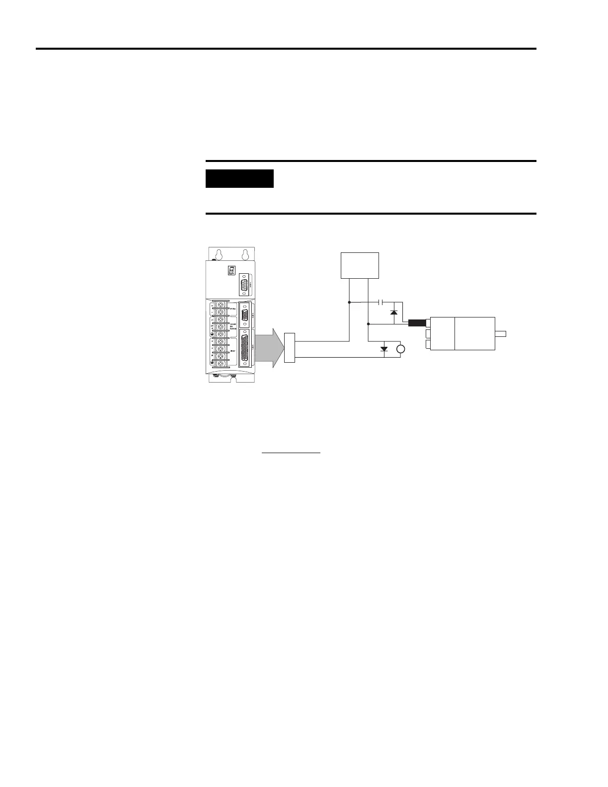
Example Configuration Controlling a Motor Brake
(1)
Flyback diode (1N4004 rated 1.0 A @ 400V dc) suppresses collapsing field of brake coil.
(2)
For non-SERCOS drive, the relay output (CN1-43 and CN1-44) must be configured as a brake.
For more information on minimizing electrical noise, refer to the
System Design for Control of Electrical Noise Reference Manual,
publication GMC-RM001
.
Electrical arcing may occur at the relay contacts until the brake
power dissipates. A customer-supplied diode or metal oxide
varistor (MOV) is recommended to prevent arcing.
CN1
43
44
N.O. Relay Output +
N.O. Relay Output -
CR1
Brake
Feedback
Power
Power Supply
3 A @ 24V dc
+
_
CR1
(1)
(2)
(1)
 Loading...


