Publication 2098-IN005C-EN-P — March 2008
162 Minimizing the Effects of Feedback Signal Loss
Change the Default Trending Dialog Settings
You can change the X or Y scales of the trending dialog (time base
and amplitude, respectively) or the sampling period of the acquisition
cycle by using the RSTrendX chart properties control panel.
Follow these steps to change the default trending dialog settings.
1. Right-click the trending dialog and choose Chart Properties.
The RSTrendX Properties dialog opens.
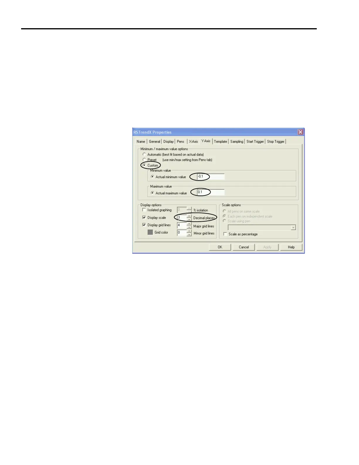
2. Click the Y-Axis tab.
3. Under Display options, change the number of decimal places to 3
(or more), depending on the resolution needed for your
application.
4. Click Apply.
5. Click OK to close the RSTrendX dialog.
6. Observe the trending dialog waveform again.
Make note of the positive and negative excursion limit values for
position error waveform.
7. Right-click the trending window and click the Y-Axis tab.
The Y-Axis tab opens again.
8. Under Minimum/maximum value options, click Custom.
9. Set the Minimum and Maximum values to capture the positive and
negative excursion limit range observed in your application.
 Loading...


