Publication 2098-IN005C-EN-P — March 2008
Commissioning Your Ultra3000 Drive 43
15. Click OK.
The Monitor Status dialog closes and the setup changes take
affect.
16. Apply 12…24V dc to input 1.
Input 1 was configured as Drive Enable in a previous step.
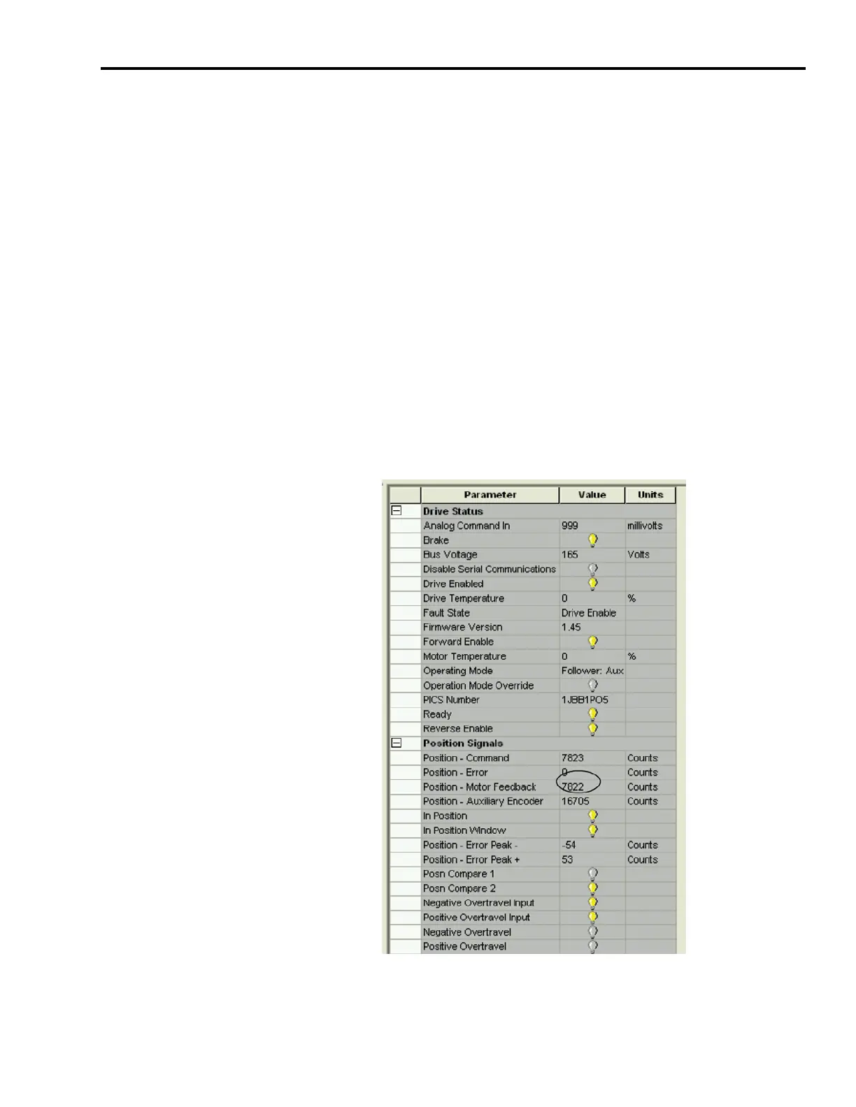
a. Verify the toolbar Enable icon is active, indicating the drive is
enabled.
b. Verify the Drive Enabled lamp is ON (yellow)
c. If none of the Presets are ON, move the auxiliary encoder and
observe the motor rotate at Preset 0 Gear Ratio or 1:1.
17. Apply 12…24V dc to Preset Select 0 which is configured for
Digital Input 8 or pin CN1-38.
Notice that the auxiliary encoder uses Preset 1 as the Gear Ratio or
2:1. This means for every two revolutions of the auxiliary encoder,
the motor rotates 1 revolution.
18. Remove the 12…24V dc (Drive Enable) from input 1.
19. Close the Monitor Branch and Digital Inputs dialog.

 Loading...


