Publication 2098-IN005C-EN-P — March 2008
Commissioning Your Ultra3000 Drive 69
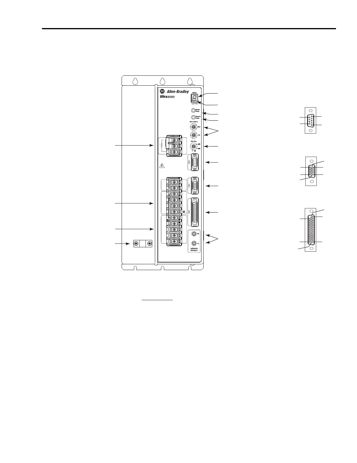
Use this figure to locate the front panel connections on the
Ultra3000-SE 460V drives (3 kW, 5 kW, 10 kW, 15 kW, and 22 kW).
Front Panel Connections for 2098-DSD-HVxxx-SE Drives
For CN1, CN2, and CN3 connector pin-out information, refer to the
Ultra3000 Digital Servo Drives Installation Manual, publication
2098-IN003
.
W
V
U
+
-
L3
L2
L1
L1
AUX
L2
AUX
Motor
DC Bus
230-480 VAC
50/60 Hz
Internal
External Shunt
1
2
3
TB2
DANGERDANGER
Hazardous voltage
exists after power down.
TB1
Pin 11
Pin 6
Pin 15
Pin 1
Pin 10
Pin 5
Pin 30
Pin 44
Pin 1
Pin 15
Pin 16
Pin 31
Pin 6
Pin 9
Pin 1
Pin 5
8
AC Input Power
Connections
Motor Power
Connections
Passive Shunt
Resistor Connections
Seven-segment
Status Indicator
Logic Power Status Indicator
CN3 9-pin
Serial Port
Connector
CN2 15-pin
Motor Feedback
Connector
CN1 44-pin
User I/O
Connector
SERCOS interface
Receive (Rx) and
Transmit (Tx)
Connectors
Node Address Switches
Data Rate Switch
Module Status Indicator
Network Status Indicator
Motor Power
Cable Shield Clamp
9-pin CN3
Serial Connector
15-pin CN2
Feedback Connector
44-pin CN1
I/O Connector
 Loading...


