36 Rockwell Automation Publication DRIVES-AT005D-EN-P - May 2022
Chapter 3 Shared DC Bus Configuration (Piggyback)
6. The calculated total deceleration output power, PDecel, is a negative value indicating line regeneration is required. Select a PowerFlex 755TR
regenerative AC drive.
7. The highest AC output absolute value power total is 55.0 kW heavy duty (HD). Use this value to select the minimum AC output power for the
PowerFlex 755TR AC drive.
8. From Table 25 on page 108
in Appendix C, the minimum AC output power rating 480V AC PowerFlex 755TR drive is a 20G…D125 frame 6 with
an AC output HD power rating of 75 HP (56 kW). The 20G...D125 AC drive can only support a maximum external capacitance of 880 uF. Select
the 20G...D186 AC drive that can support a maximum external capacitance of 2184 uF.
9. Motor 2, the 45 kW AC motor connected to the 125 HP (93 kW) HD PowerFlex 755TR AC drive, has a power ratio of 93 kW/45 kW= 2.07:1. This is
very close to the recommended 2:1 ratio.
10. Verify that the PowerFlex 755TR AC drive is capable of precharging the external DC bus capacitance.
• All drive products are rated for 480V AC system power voltage.
• The PowerFlex 750-Series internal DC bus capacitance data is taken from Table 9 on page 66
in Appendix A.
• The PowerFlex 755TL/TR maximum external DC bus capacitance data is taken from Table 25 on page 108
in Appendix C.
The total external capacitance (1905 µF) is less the PowerFlex 755TL/TR maximum external capacitance (2184 µF).
The chosen PowerFlex 755TR AC drive is capable of precharging the shared DC bus capacitance
11. Use the tables in Appendix A
to determine the rated DC input currents for each external connected inverter/drive. Size the DC power cables/
bus bars feeding each external inverter/drive for the rated DC input current.
In this example, the total rated DC amps for the external connected inverter/drives is 23.3 A DC + 8.1 A DC = 31.4 A DC. The chosen PowerFlex
755TL/TR AC drive is an acceptable solution for this shared DC bus application example.
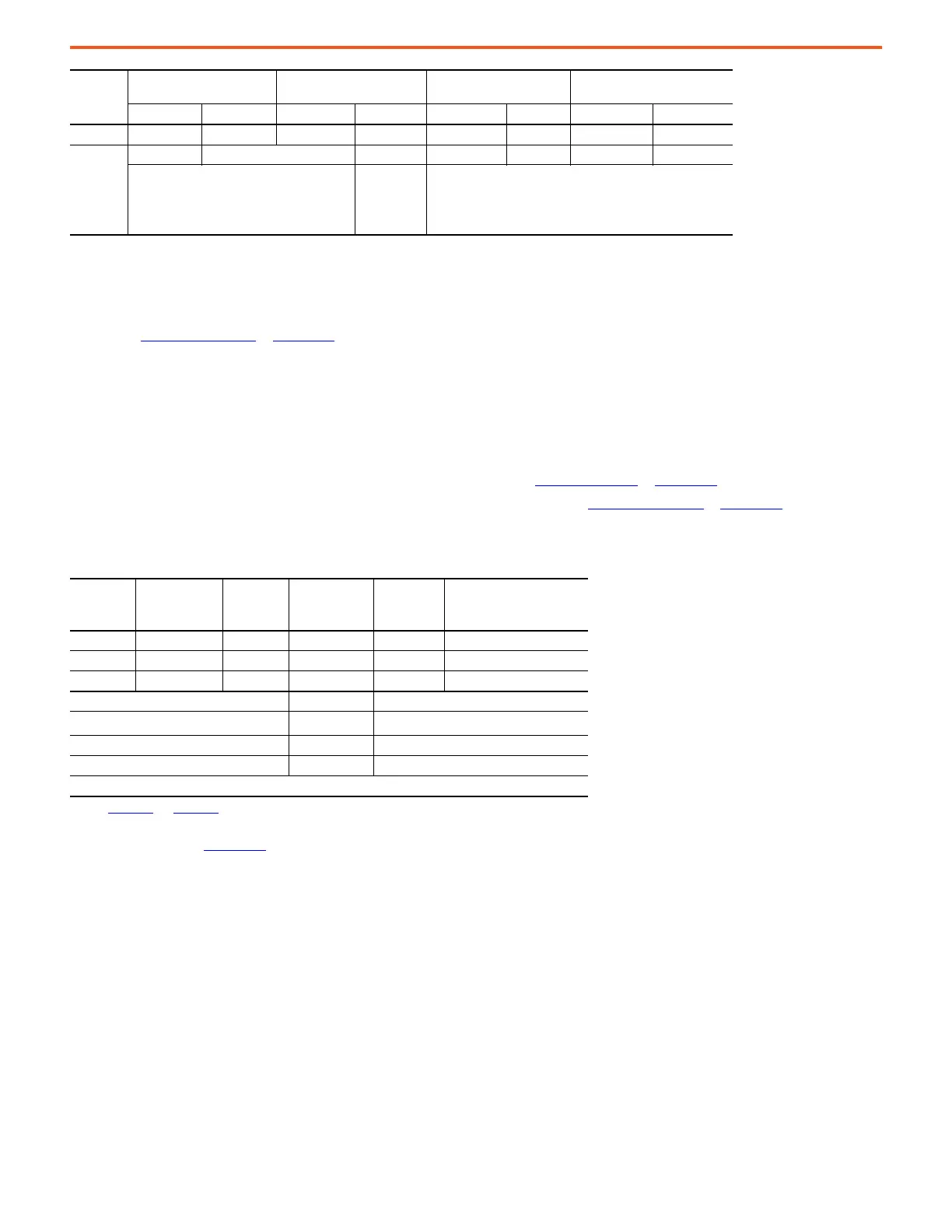
Motor 3 5 0.92 6.70 7.28 3.50 3.80 -6.00 -5.52
Bus Supply
OL Duty
None=1.0
ND = 1.1
HD = 1.5
1.5 Output Power Totals 54.4 55.0 -24.0
Bus Supply Min Output Power Rating 55.0 kW HD
Section
Name Drive Product Cat. No.
Internal DC Bus
Capacitance
(µF)
(1)
(1) See Appendix A and Appendix C for internal and maximum capacitance values.
Rated DC
Input Amps Notes
Motor 1 PowerFlex 755 20G…D027 1200 23.3 Frame 3, HD
Motor 2 PowerFlex 755TR 20G…D186 13800 – Frame 6, HD bus supply
Motor 3 PowerFlex 755 20G…D011 705 8.1 Frame 2, HD
PF755TL/TR Max External Capacitance 2184 µF
Total External Capacitance
(2)
(2) The PF755TR internal DC bus capacitance isn’t included in the total external capacitance calculation.
1905 µF
Total DC Bus Capacitance 15705 µF
Total DC rated Amps 31.4 A DC
Precharge OK
Section
Name
Motor Nameplate
Accel Drive Output Power
(kW)
Run Drive Output Power
(kW) Decel Drive Output Power (kW)
Power (kW) Efficiency PMaccel PAccel PMrun PRun PMdecel PDecel

 Loading...


