3-58 Programming and Parameters
Selected Option Definitions – [Analog Outx Sel], [Digital Inx Sel],
[Digital Outx Sel]
INPUTS & OUTPUTS (File J)
Digital Outputs
383
387
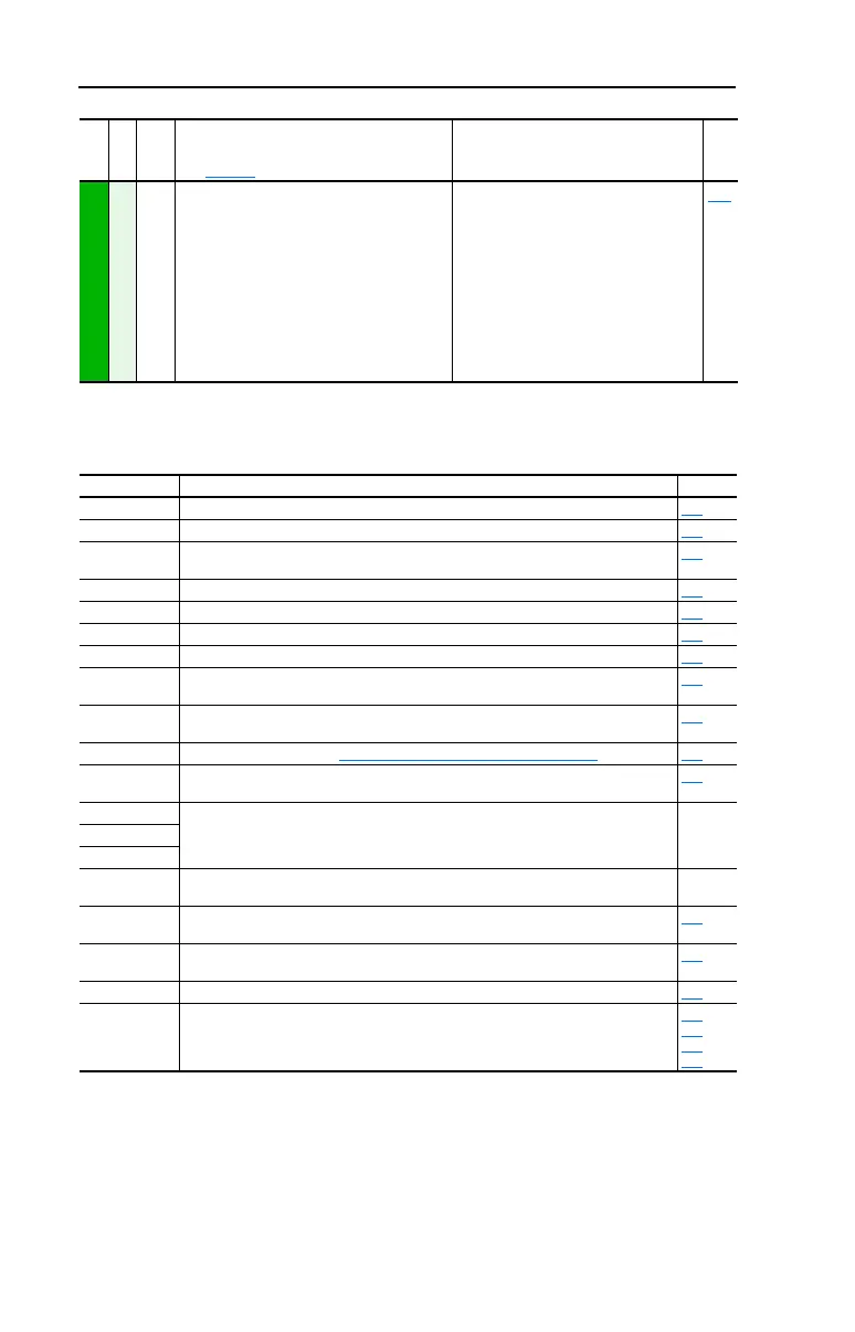
[Dig Out1 OffTime]
[Dig Out2 OffTime]
Sets the “OFF Delay” time for the digital
outputs. This is the time between the
disappearance of a condition and
de-activation of the relay.
Default:
Min/Max:
Units:
0.0 Secs
0.0 Secs
0.0/600.0 Secs
0.1 Secs
380
File J
Group
No.
Parameter Name and Description
See page 3-2 for symbol descriptions
Values
Related
Option Description Related
At Speed Relay changes state when drive has reached commanded speed. 380
Excl Link Links digital input to a digital output if the output is set to “Input 1-6 Link.” 361
Input 1-6 Link When Digital Output 1 is set to of these (i.e. Input 3 Link) in conjunction with Digital Input
3 set to “Excl Link,” the Digital Input 3 state (on/off) is echoed in the Digital Output 1.
380
Manual Mode Either the HIM or I/O Terminal Block (analog input) has control of the speed reference. 380
MOP Dec Decrements speed reference as long as input is closed. 361
MOP Inc Increments speed reference as long as input is closed. 361
MtrTrqCurRef Torque producing current reference. 342
Param Cntl Parameter controlled analog output allows PLC to control analog outputs through data
links. Set in [AnlgX Out Setpt], parameters 377-378.
342
Param Cntl Parameter controlled digital output allows PLC to control digital outputs through data
links. Set in [Dig Out Setpt], parameter 379.
342
PI Reference Reference for PI block (see Process PI for Standard Control on page C-11). 342
Precharge En Forces drive into precharge state. Typically controlled by auxiliary contact on the
disconnect at the DC input to the drive.
361
Run Level Provides a run level input. They do not require a transition for enable or fault, but a
transition is still required for a stop.
RunFwd Level
RunRev Level
Run w/Comm Allows the comms start bit to operate like a run with the run input on the terminal block.
Ownership rules apply.
SpdFdBk NoFilt Provides an unfiltered value to an analog output. The filtered version “Speed Fdbk”
includes a 125 ms filter.
342
Sync Enable The fiber feature Synchronized Speed Change has been enabled. Allows a coordinated
change in drive speeds to change machine speed.
622
Torque Est Calculated percentage of rated motor torque. 342
Traverse Enable The Traverse function has been enabled. This adds a triangle wave and square wave
modulation to the speed reference.
623
624
625
626
 Loading...